Device and method for signal processing

a signal processing and digital signal technology, applied in the field of signal processing technology, can solve the problems of insufficient performance, inability to easily convert digital output from a sigma-delta modulator into an analog voltage,

Inactive Publication Date: 2006-06-06
ESS TECHNOLOGY
View PDF21 Cites 34 Cited by
  • Summary
  • Abstract
  • Description
  • Claims
  • Application Information

AI Technical Summary

Benefits of technology

[0011]In another aspect, the invention features a digital circuit for suppressing distortion in a digital signal that exists after a pulse width modulation, wherein the pulse width modulation occurs at a clock rate, and wherein the digital circuit includes a digital filter configured to receive the signal having the distortion and to sample the signal at the clock rate.
[0016]In still another aspect, the invention features a method including modulating a first pulse code modulated signal having a first resolution into a second pulse code modulated signal having a second resolution, wherein the second resolution is smaller than the first resolution. In such an aspect, the method also includes modulating the second pulse code modulated signal into a third signal that has a plurality of pulses in time generated at a clock rate, and further includes filtering in a digital domain the plurality of pulses in time to suppress a distortion in the third signal.

Problems solved by technology

However, one disadvantage of such a technique (at least for certain audio equipment applications) is that digital output from a sigma-delta modulator may not be easily converted into an analog voltage due to variable frequencies present in the data stream.
However, such performance may be insufficient or unacceptable in certain circumstances or for particular users.

Method used


Image

  • Device and method for signal processing
  • Device and method for signal processing
  • Device and method for signal processing

Examples


Embodiment Construction

[0030]Various embodiments of devices, systems and methods in accordance with embodiments of the present invention will now be described with reference to the drawings.

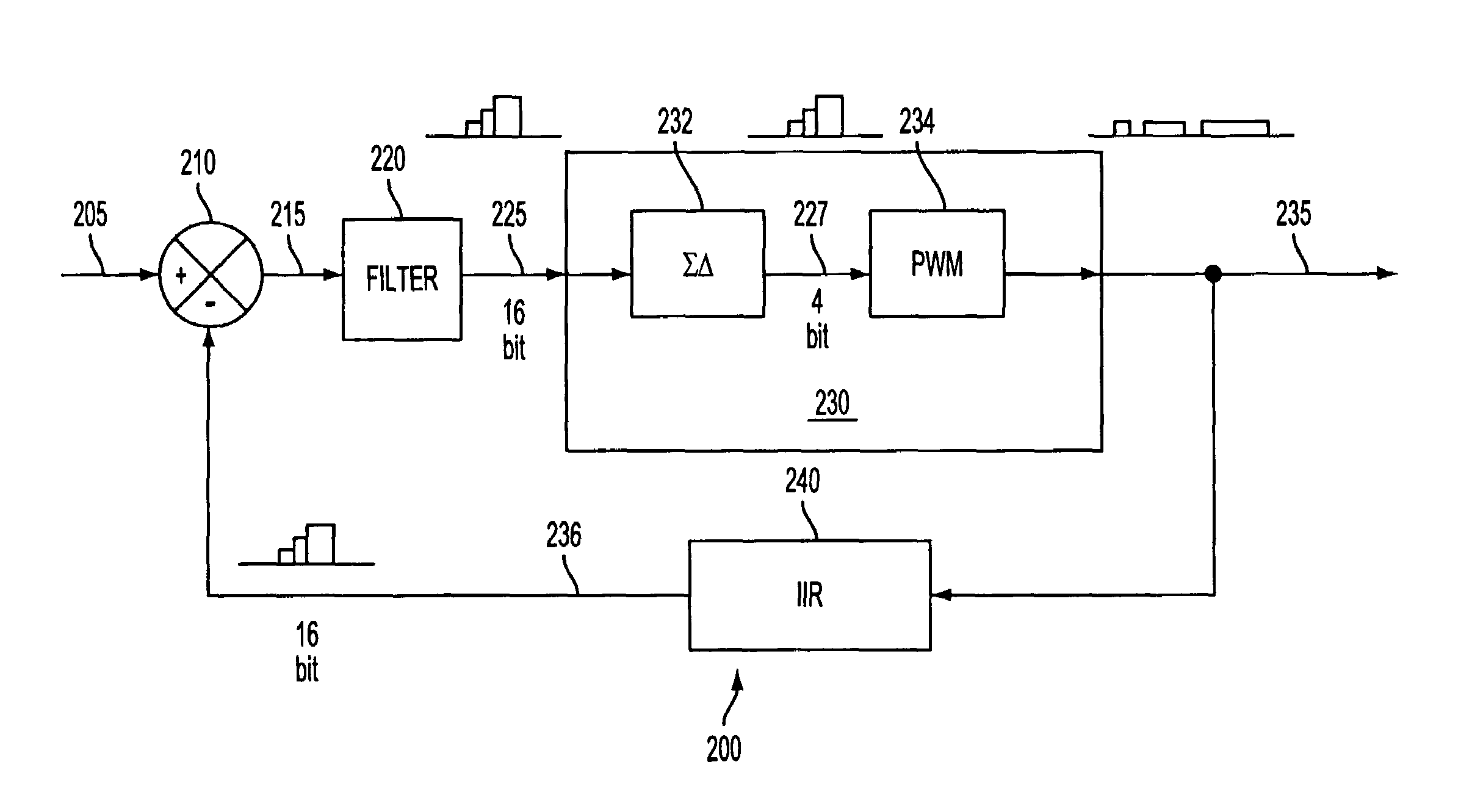
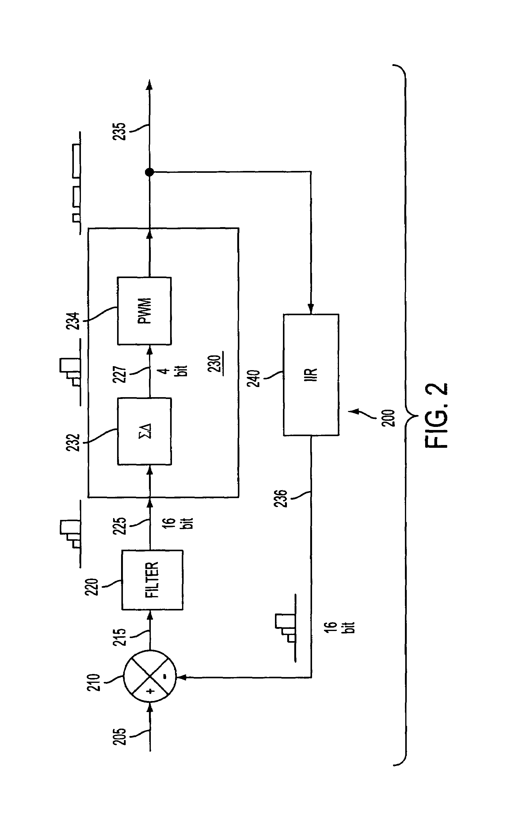
[0031]In one embodiment of the present invention, a signal processor 200 receives a digital wide-bit input signal and uses feedback that is entirely in the digital domain to correct for any error that may be introduced into the output signal 235 by the process of pulse width modulating the input signal 205. Various embodiments of the present invention may include, for example, (1) an integrated circuit chip 501 for use in an optical disk player (e.g., a digital versatile disk (DVD) player), wherein the chip 501 contains at least two signal processors 200-1, 200-2 (i.e., one for left channel output and the other for right channel output), (2) an integrated circuit chip 551 for use in a surround sound audio power amplifier, wherein the chip 551 may contain eight signal processors 200-1 to 200-8 (i.e., one for each of eig...


PUM


Abstract

The present invention relates to a signal processor and methods of using a signal processor. In one aspect, the present invention relates to a signal processor that includes a pulse width modulator having a clock rate, and also includes a digital filter configured to receive an output of the pulse width modulator, wherein the digital filter samples the output at the clock rate to suppress the distortion. In another aspect, the present invention relates to a method including modulating a first pulse code modulated signal having a first resolution into a second pulse code modulated signal having a second resolution that is smaller than the first resolution. This aspect further includes modulating the second pulse code modulated signal into a third signal that includes a plurality of pulses in time having a clock rate, and filtering in a digital domain the plurality of pulses in time to suppress a distortion in the third signal.

Description

FIELD OF THE INVENTION[0001]The present invention relates to signal processing technology and, more particularly, to devices and methods for processing digital signals such as, for example, digital audio signals.BACKGROUND OF THE INVENTION[0002]It has been documented that a digital-to-analog converter may be used to process digitized signals for amplification by an analog power amplifier. For example, Erik Bresch and Wayne T. Padgett in “TMS320C67-Based Design Of A Digital Audio Power Amplifier Introducing Novel Feedback Strategy” (http: / / www.ti.com / sc / docs / general / dsp / fest99 / poster / hbreschpadgett.pdf) describe such an amplification technique used in connection with audio signals. FIG. 1 shows a basic structure of a Class-D type audio power amplifier as depicted by Bresch and Padgett.[0003]Certain digital audio signal sources, such as compact disk (CD) players, provide digitized audio signals that are pulse code modulated. Such digitized audio signals may have a 16-bit resolution an...

Claims


Application Information

Patent Timeline
Patent Type & Authority Patents(United States)
IPC IPC(8): G06F17/00H03F3/38H03F3/217H03F3/387
CPCH03F3/2175H03F3/387H03F2200/351H03F2200/331H03F3/38G11B20/10
Inventor MALLINSON, MARTIN
Owner ESS TECHNOLOGY
Why Eureka
Try Eureka