Image forming apparatus

a technology of forming apparatus and absorbing body, which is applied in the direction of other printing apparatus, printing after-treatment, printing, etc., can solve the problems of color material components being trailed or rubbed away, and achieve the effect of ensuring the elasticity of the absorbing body in the pressing direction and the orthogonal direction, reducing the amount of displacement of the absorbing body, and relatively easy to achiev

Inactive Publication Date: 2006-09-28
FUJIFILM CORP
View PDF4 Cites 34 Cited by
  • Summary
  • Abstract
  • Description
  • Claims
  • Application Information

AI Technical Summary

Benefits of technology

[0012] According to this aspect, the absorbing body is constituted by combining the surface layer and the supporting layer, and hence it is possible to ensure the elasticity of the absorbing body in the pressing direction and the orthogonal direction required in the present invention relatively easily.
[0013] According to the present invention, when the absorbing body is pressed against the object liquid, it is possible to suppress the amount of displacement of the absorbing body in “the orthogonal direction which is perpendicular to the pressing direction against the object liquid”. Accordingly, when the absorbing body is pressed against the object liquid, then it is possible to effectively prevent the absorbing body from applying an excessive force to the coloring material contained in the object liquid, in a direction perpendicular to the pressing direction.

Problems solved by technology

Furthermore, if all of the ink droplets deposited on the recording medium are dried, then the printed regions on the recording medium may rise up in a projecting fashion, and this may be undesirable depending on the use of the printed object.
As described above, several devices for removing solvent component from an object liquid by absorbing it with an absorbing body have been proposed, but there has not yet been a proposal for a device which focuses on the anisotropy of the elastic modulus of the absorbing body.
Furthermore, if the absorbing body is displaced in the horizontal direction when it is pressed against the object liquid, then the coloring material component may be trailed or rubbed away by the absorbing body.

Method used


Image

  • Image forming apparatus
  • Image forming apparatus
  • Image forming apparatus

Examples


first embodiment

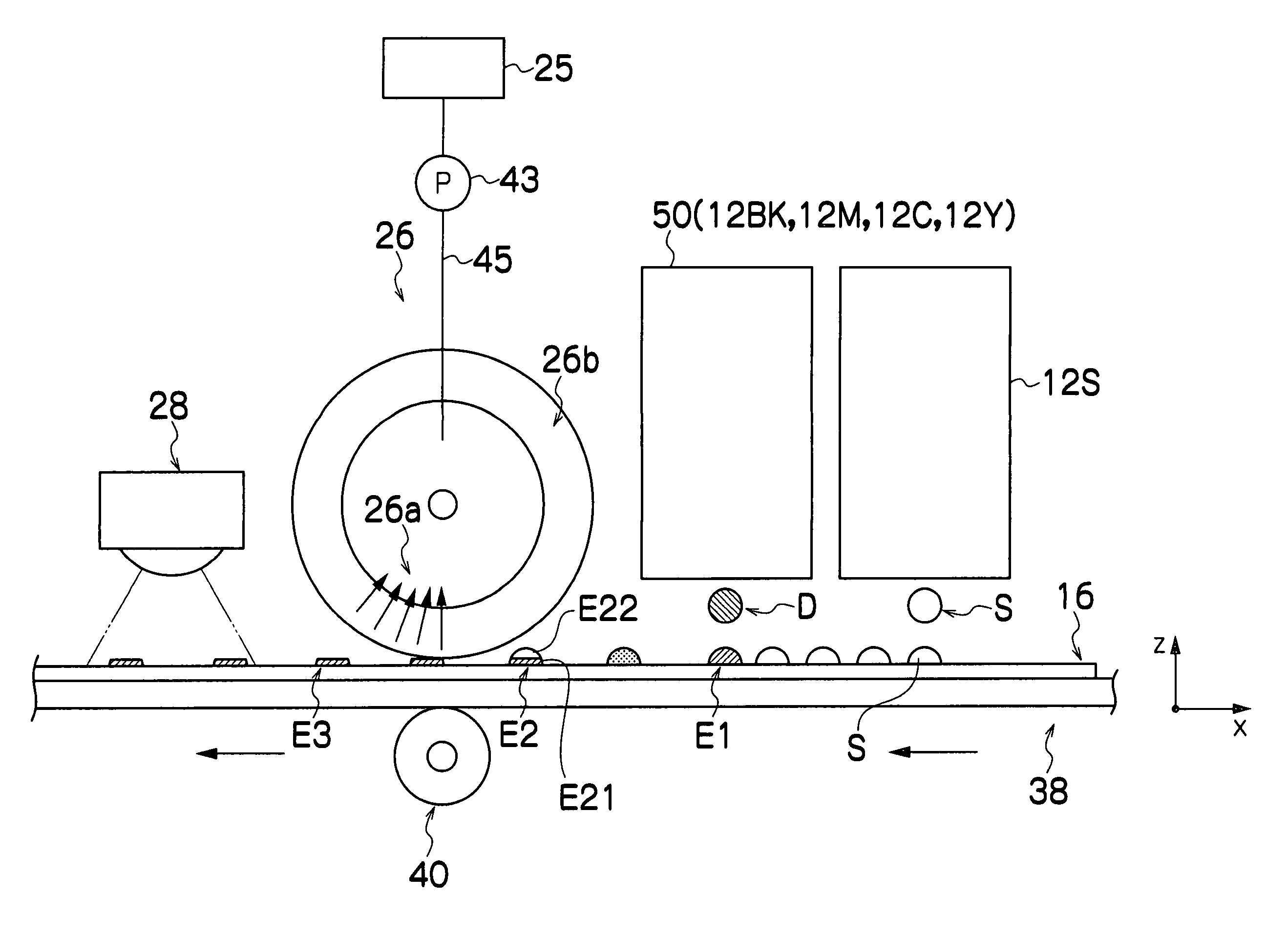
[0034] In the present embodiment, a radiation-curable ink containing a coloring material and a solvent is used. This radiation-curable ink is separated into a coloring material component and a solvent component by reaction with a treatment liquid. A portion of the solvent component is absorbed by a solvent absorbing body, while the remaining radiation-curable ink is fixed by irradiation of radiation. Consequently, the radiation-curable ink is cured in a flattened state on the recording medium.

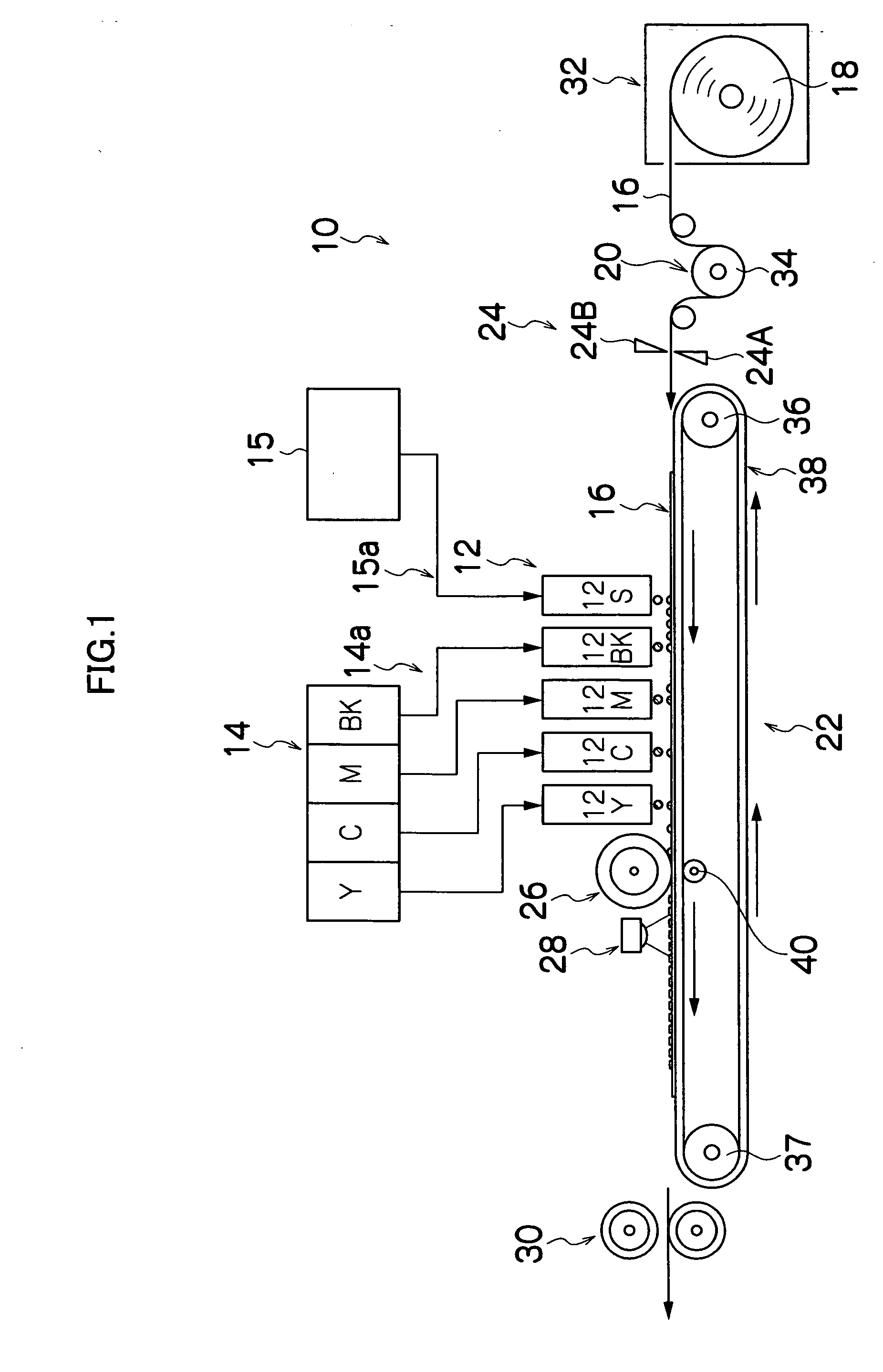
[0035]FIG. 1 shows a general view of the overall composition of an inkjet recording apparatus 10 according to a first embodiment of the present invention. The inkjet recording apparatus 10 according to this embodiment comprises: a paper supply unit 18 which supplies recording paper 16; a decurling unit 20 provided after the paper supply unit 18; a cutter 24 provided after the decurling unit 20; a print unit 12 provided after the cutter 24; a solvent absorbing roller 26 provided after the print...

second embodiment

[0121] The present embodiment is substantially the same as the first embodiment described above, parts which are the same as those of the first embodiment being labeled with the same reference numerals and detailed description thereof being omitted here.

[0122]FIG. 11 shows a general view of the overall composition of the inkjet recording apparatus 10 in a second embodiment. In the present embodiment, the treatment liquid heads, solvent absorbing rollers and auxiliary rollers are provided so as to correspond respectively to the print heads (ink heads) 12BK, 12M, 12C and 12Y.

[0123] With respect to the print heads 12BK, 12M, 12C and 12Y, treatment liquid heads 12S-BK, 12S-M, 12S-C and 12S-Y are provided respectively on the upstream side in terms of the conveyance direction of the recording paper 16, and solvent absorbing rollers 26BK, 26M, 26C and 26Y, and auxiliary rollers 40BK, 40M, 40C and 40Y, are provided respectively on the downstream side.

[0124] The radiation source 28 is sit...

third embodiment

[0128] The present embodiment is substantially the same as the second embodiment described above, parts which are the same as those of the second embodiment being assigned with the same reference numerals and detailed description thereof being omitted here.

[0129]FIG. 12 shows a general view of the overall composition of the inkjet recording apparatus 10 in a third embodiment. In order to separate the coloring material component and the solvent component in the ink ejected from the print heads 12BK, 12M, 12C and 12Y, the second embodiment described above relates to an example in which a treatment liquid is mixed with the ink. In contrast, in the present embodiment, a so-called electrophoretic effect is used. Therefore, in the present embodiment, corona chargers 96BK, 96M, 96C and 96Y are provided instead of the treatment liquid heads 12S-BK, 12S-M, 12S-C and 12S-Y.

[0130] As shown in FIG. 12, the auxiliary rollers 40BK, 40M, 40C and 40Y, the corona chargers 96BK, 96M, 96C and 96Y, a...


PUM


Abstract

The image forming apparatus comprises: an object liquid ejection device which ejects object liquid containing coloring material and solvent, onto a recording medium; a separating device which separates the coloring material and the solvent in the object liquid ejected on the recording medium; and a solvent removal device including an absorbing body which absorbs the solvent, the absorbing body being pressed against the object liquid in which the coloring material and the solvent are separated by the separating device, wherein an elastic modulus En of the absorbing body in a pressing direction in which the absorbing body is pressed against the object liquid ejected on the recording medium, and an elastic modulus Es of the absorbing body in an orthogonal direction perpendicular to the pressing direction, satisfy the following relationship: En<Es.

Description

BACKGROUND OF THE INVENTION [0001] 1. Field of the Invention [0002] The present invention relates to an image forming apparatus, and more particularly, to an absorbing body which absorbs a solvent component from an object liquid containing a coloring material component and the solvent component. [0003] 2. Description of the Related Art [0004] In recent years, inkjet recording apparatuses (inkjet printers) have become widespread as image forming apparatuses for printing images. An inkjet recording apparatus prints a desired image by ejecting ink droplets from an inkjet recording head, onto a recording medium, such as a sheet of recording paper, while the recording medium and the inkjet recording head are moved relatively with respect to each other. From the viewpoint of preventing bleeding, and the like, in an inkjet recording apparatus of this kind, it is desirable that the ink droplets deposited on the recording medium be dried quickly, so that the image is fixed rapidly on the rec...

Claims


Application Information

Patent Timeline
Patent Type & Authority Applications(United States)
IPC IPC(8): B41J2/165
CPCB41J2/2114B41J11/0015B41J11/002B41J11/007B41J11/70B41J13/03B41J13/076B41J15/165B41M7/00B41J11/00214
Inventor HIRAKAWA, TAKASHI
Owner FUJIFILM CORP
Why Eureka
Try Eureka