
Behind-the-ear hearing device with a magnetically-attached ear hook

a hearing device and magnetic connection technology, applied in the direction of hearing aid mounting/interconnection, deaf-aid sets, electric devices, etc., can solve the problems of not being able to rotate about the longitudinal axis, the connection normally predetermines a fixed position, and the screwed ear hook cannot be re-used

Inactive Publication Date: 2008-08-28
SIEMENS AUDIOLOGISCHE TECHN
View PDF6 Cites 26 Cited by
  • Summary
  • Abstract
  • Description
  • Claims
  • Application Information

AI Technical Summary

Benefits of technology

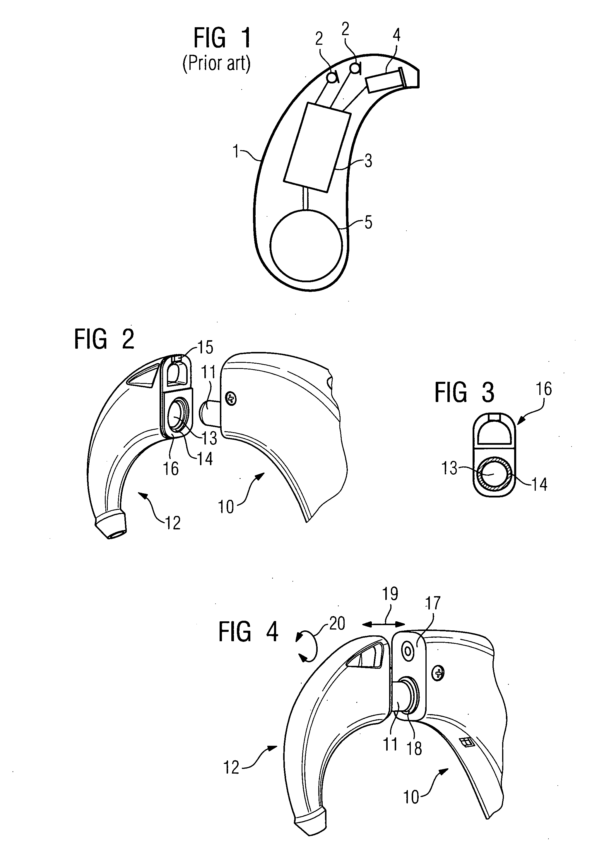
"The present invention is about a behind-the-ear hearing device with a hearing device housing and ear hook that can be easily attached to the housing. The ear hook can be clipped onto the housing and is used to attach the hearing device to the ear of a hearing device wearer. The two parts are detachably fastened to each other in an axial direction in respect of the sound outlet tube by means of a magnetic connection. The magnetic connection allows the ear hook to be securely attached to the housing and ensures tight leak tightness. The attachment process is simple without screws. The magnetic connection uses an annular magnet which is arranged at the edge of the opening or around the sound outlet tube. A ferromagnetic section of the parts can be used as a magnetic counterpiece for the magnetic connection. The two parts can also be rotated about the axis of the sound outlet tube when attached to each other, allowing for individual adjustment of the ear hook angle. A gap no longer exists between the two parts when joined, preventing dirt from entering. A catch and recess can be used to securely attach the ear hook to the hearing device housing."

Problems solved by technology

As a result of the mechanical tolerances, a connection of this type does not ensure firm positioning and is thus generally only used with lower priced hearing devices.
Furthermore, this connection normally predetermines a fixed angular position of the ear hook in respect of the hearing device housing.
It is not able to rotate about its longitudinal axis.
This will however influence the functionality of the ear hook, since the connection between the ear hook and the hearing device housing is then not tightly sealed.
Usually a screwed ear hook cannot be re-used.

Method used


Image

  • Behind-the-ear hearing device with a magnetically-attached ear hook
  • Behind-the-ear hearing device with a magnetically-attached ear hook

Examples


Embodiment Construction

[0024]The embodiments illustrated in more detail below represent preferred exemplary embodiments of the present invention.

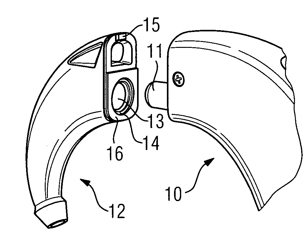
[0025]A hearing device housing 10 with a sound outlet tube connecting piece 11 is provided in accordance with the example in FIG. 1. This connecting piece is embodied purely in the manner of a tube and does not have any thread.

[0026]FIG. 2 also shows an ear hook 12, which is to be attached to the hearing device housing 10. The ear hook 12 has a sound opening 13 on its front side 16, which is to rest against the hearing device housing 10, into which sound opening 13 the sound outlet tube connecting piece 11 is to be inserted. A ring magnet 14 is arranged around this sound opening 13. It interacts with a magnetic or ferromagnetic ring, which is arranged around the sound outlet tube connecting piece 11, and is not visible in FIG. 2 (but is by contrast visible in FIG. 4). The ring magnet 14 causes the ear hook 12 to be drawn in the direction of the longitudinal axis ...


PUM


Abstract

An ear hook is to be able to be tightly attached to a hearing device housing in a simple fashion. To this end, provision is made for it to be possible to clip the ear hook onto the hearing device housing. One of the two parts; hearing device housing and ear hook has a sound outlet tube, which can be inserted into a corresponding opening in the other part. The two parts are detachably fastened to one another in an axial direction in respect of the sound outlet tube by means of a magnetic connection. The magnetic connection ensures that the two components are fitted tightly onto one another, though it enables said two components to rotate in respect of each other.

Description

CROSS REFERENCE TO RELATED APPLICATIONS[0001]This application claims priority of German application No. 10 2007 008 737.5 filed Feb. 22, 2007, which is incorporated by reference herein in its entirety.FIELD OF THE INVENTION[0002]The present invention relates to a behind-the-ear hearing device with a hearing device housing and an ear hook, which can be clipped onto the hearing device housing and which is used to attach the behind-the-ear hearing device to an ear of a hearing device wearer.BACKGROUND OF THE INVENTION[0003]Hearing devices are portable hearing apparatuses which are used to supply the needs of the hard-of-hearing. To accommodate the numerous individual requirements, different configurations of hearing devices such as behind-the-ear hearing devices (BTE), in-the-ear hearing devices (ITE), e.g. including conch hearing devices or channel hearing devices (CIC), are provided. The hearing devices designed by way of example are worn on the outer ear or in the auditory canal. Fu...

Claims


Application Information

Patent Timeline
Patent Type & Authority Applications(United States)
IPC IPC(8): H04R25/00
CPCH04R25/60H04R2225/63H04R2225/0213H04R25/607
Inventor HO, WAI KIT DAVIDKOO, WEE HAWTAN, BENG HAI
Owner SIEMENS AUDIOLOGISCHE TECHN
Learn More