Golf ball dimples with a catenary curve profile

Inactive Publication Date: 2008-09-11
ACUSHNET CO
View PDF43 Cites 99 Cited by
  • Summary
  • Abstract
  • Description
  • Claims
  • Application Information

AI Technical Summary

Benefits of technology

[0022]In one embodiment, about 50 percent or more of the dimples on the golf ball are defined by the catenary curve expression above. In another embodiment, about 80 percent or more of the dimples on the golf ball are defined by the catenary curve expression. In this aspect of the invention, D may range from about 0.100 inches to about 0.225 inches, sf from about 5 to about 200, and d

Problems solved by technology

However, in the late nineteenth century, players observed that, as golf balls became scuffed or marred from play, the balls achieved more distance.
These improvements have come at great cost to manufacturers.
For example, to determine if a particular ball design has desirable flight characteristics for a broad range of players, i.e., high and low swing speed players, manufacturers perform the mechanical golfer test with different ball launch conditions, which involves immense time and financial commitments.
Furthermore, it is difficult to identify incremental performance improvements using these methods due to the statistical noise generated by environmental conditions, which necessitates large sample sizes for sufficient confidence intervals.
It results from a difference in pressure that is created by a distortion in the air flow that results from the back spin of the ball.
The difference between the high pressure in front of the ball and the low pressure behind the ball reduces the ball speed and

Method used


Image

  • Golf ball dimples with a catenary curve profile
  • Golf ball dimples with a catenary curve profile
  • Golf ball dimples with a catenary curve profile

Examples


Embodiment Construction

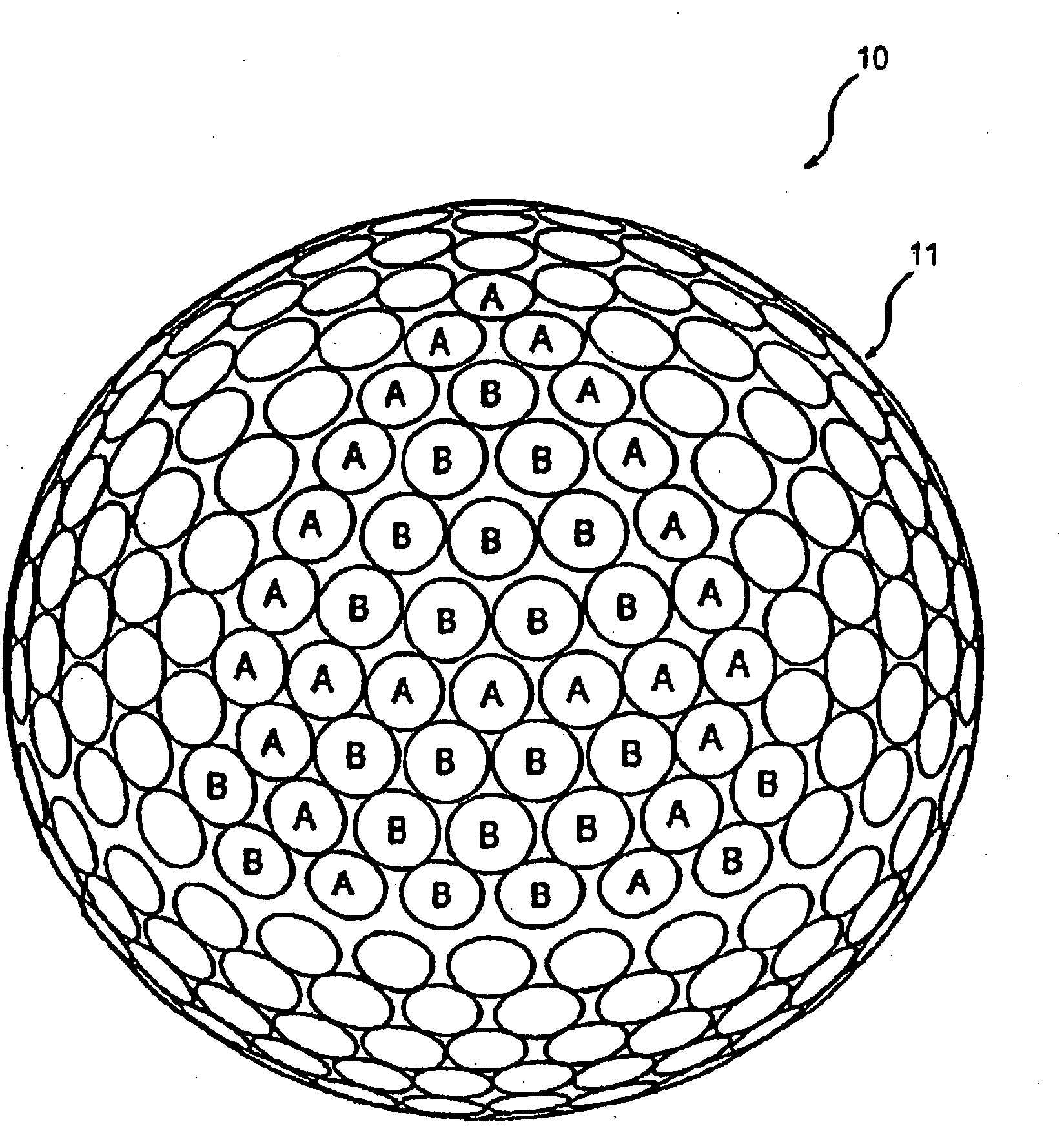
[0051]The present invention is directed to golf balls having improved aerodynamic performance due, at least in part, to the selection of dimple arrangements and dimple profiles. In particular, the present invention is directed to a golf ball that includes at least a portion of its dimples that are defined by the revolution of a catenary curve about an axis.

[0052]The dimple profiles of the present invention may be used with practically any type of ball construction. For instance, the golf ball may have a two-piece design, a double cover, or veneer cover construction depending on the type of performance desired of the ball. Other suitable golf ball constructions include solid, wound, liquid-filled, and / or dual cores, and multiple intermediate layers. Examples of these and other types of ball constructions that may be used with the present invention include those described in U.S. Pat. Nos. 5,713,801, 5,803,831, 5,885,172, 5,919,100, 5,965,669, 5,981,654, 5,981,658, and 6,149,535, as w...


PUM


Abstract

A golf ball having an outside surface with a plurality of dimples formed thereon. The dimples on the ball have a cross-sectional profiles formed by a catenary curve. Combinations of varying dimple diameters, shape factors, and chordal depths in the catenary curve are used to vary the ball flight performance according to ball spin characteristics, player swing speed, as well as satisfy specific aerodynamic magnitude and direction criteria.

Description

CROSS-REFERENCE TO RELATED APPLICATIONS[0001]This application is a continuation-in-part of U.S. application Ser. No. 11 / 907,195, filed Oct. 10, 2007, which is a continuation of U.S. patent application Ser. No. 11 / 607,916, now abandoned, which is a continuation of U.S. patent application Ser. No. 11 / 108,812, now U.S. Pat. No. 7,156,757, which is a continuation of U.S. patent application Ser. No. 10 / 784,744, filed Feb. 24, 2004, now U.S. Pat. No. 6,913,550, which is a continuation of U.S. patent application Ser. No. 10 / 096,852, filed Mar. 14, 2002, now U.S. Pat. No. 6,729,976, which is a continuation-in-part of U.S. patent application Ser. No. 09 / 989,191, filed Nov. 21, 2001, now U.S. Pat. No. 6,796,912, and also a continuation-in-part of U.S. patent application Ser. No. 09 / 404,164, filed Sep. 27, 1999, now U.S. Pat. No. 6,358,161, which is a divisional of U.S. patent application Ser. No. 08 / 922,633, filed Sep. 3, 1997, now U.S. Pat. No. 5,957,786. The entire disclosures of the relate...

Claims


Application Information

Patent Timeline
IPC IPC(8): A63B37/14
CPCA63B37/0004A63B37/0012A63B37/002A63B37/0006A63B37/0096A63B37/0021A63B37/0032A63B37/0034A63B37/0019A63B37/00065A63B37/00215
Inventor AOYAMA, STEVENNARDACCI, NICHOLAS M.
Owner ACUSHNET CO
Why Eureka
Try Eureka