
Anti-theft lock structure

a technology of anti-theft locks and locks, applied in clothing locks, building locks, construction, etc., can solve problems such as notebook computers being stolen, and achieve the effect of enhancing the anti-theft protection of portable electronic devices

Inactive Publication Date: 2008-09-18
INVENTEC CORP
View PDF16 Cites 14 Cited by
  • Summary
  • Abstract
  • Description
  • Claims
  • Application Information

AI Technical Summary

Benefits of technology

[0008]Though the lock hole, a notebook computer in the prior art can be locked by a lock, the structure around the lock hole may still be damaged, such that the lock lost its security function, which thus causes the notebook computer to be stolen. In view of the above problem, the present invention is directed to an anti-theft lock structure, applicable to various portable electronic devices, in which when the lock structure of a portable electronic device is damaged, a second anti-theft mechanism is actuated, so as to enhance the anti-theft protection of the portable electronic device.
[0010]The effect of the present invention lies in that, when the anti-theft lock structure is damaged, the sensor generates a trigger signal to actuate a second anti-theft mechanism, i.e., a device such as a sound alarm or a hard disk anti-theft lock, so as to significantly alleviate the risk of being stolen of the portable electronic device, and meanwhile, avoid the disclosure of the confidential data in the storage device after the portable electronic device is stolen, and thereby effectively reducing the loss of an individual and an enterprise due to the portable electronic device being stolen.

Problems solved by technology

Though the lock hole, a notebook computer in the prior art can be locked by a lock, the structure around the lock hole may still be damaged, such that the lock lost its security function, which thus causes the notebook computer to be stolen.

Method used


Image

  • Anti-theft lock structure
  • Anti-theft lock structure
  • Anti-theft lock structure

Examples


Embodiment Construction

[0022]The objectives, structures, features, and functions of the present invention will be illustrated below in detail through the embodiments.

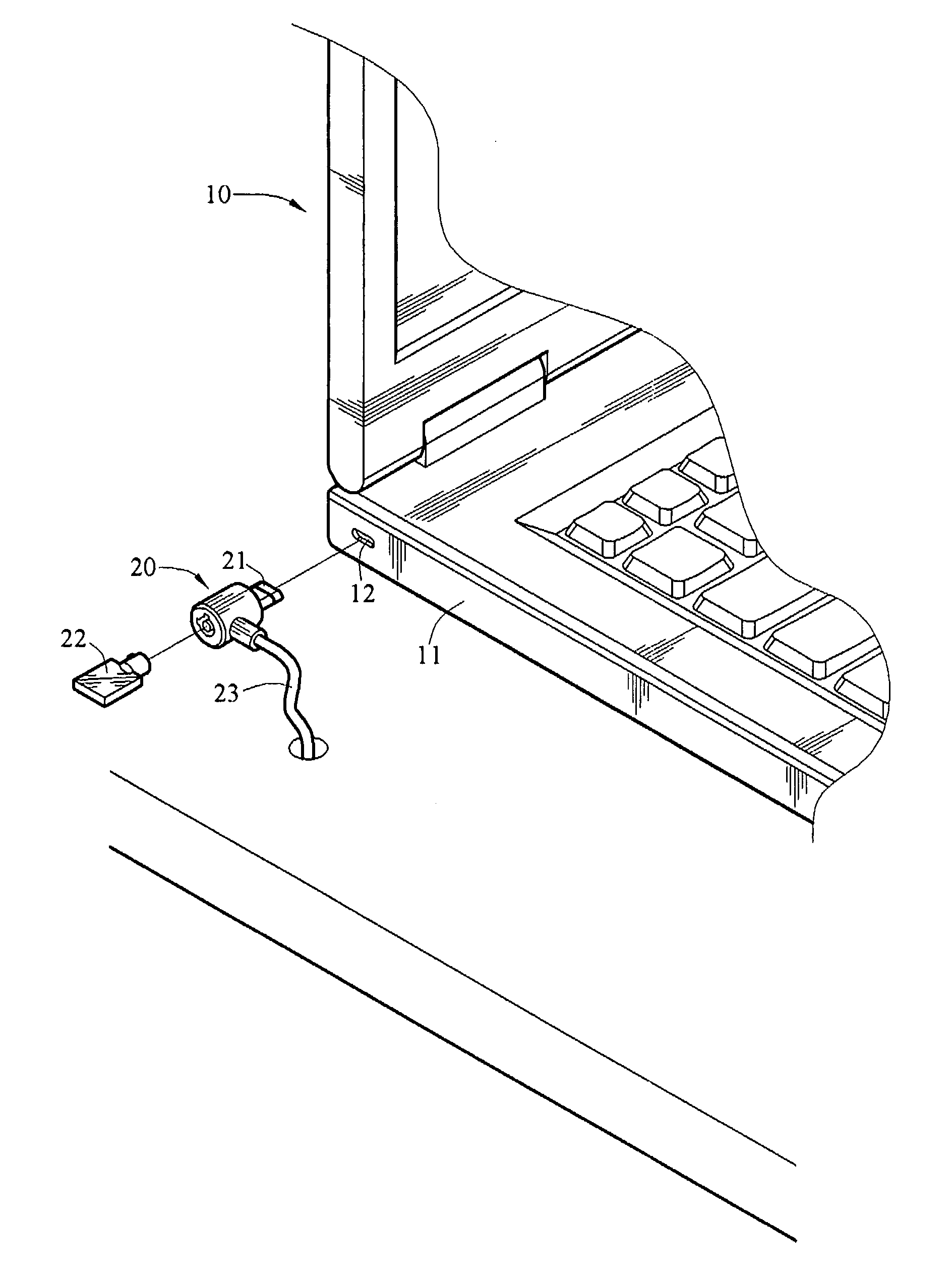
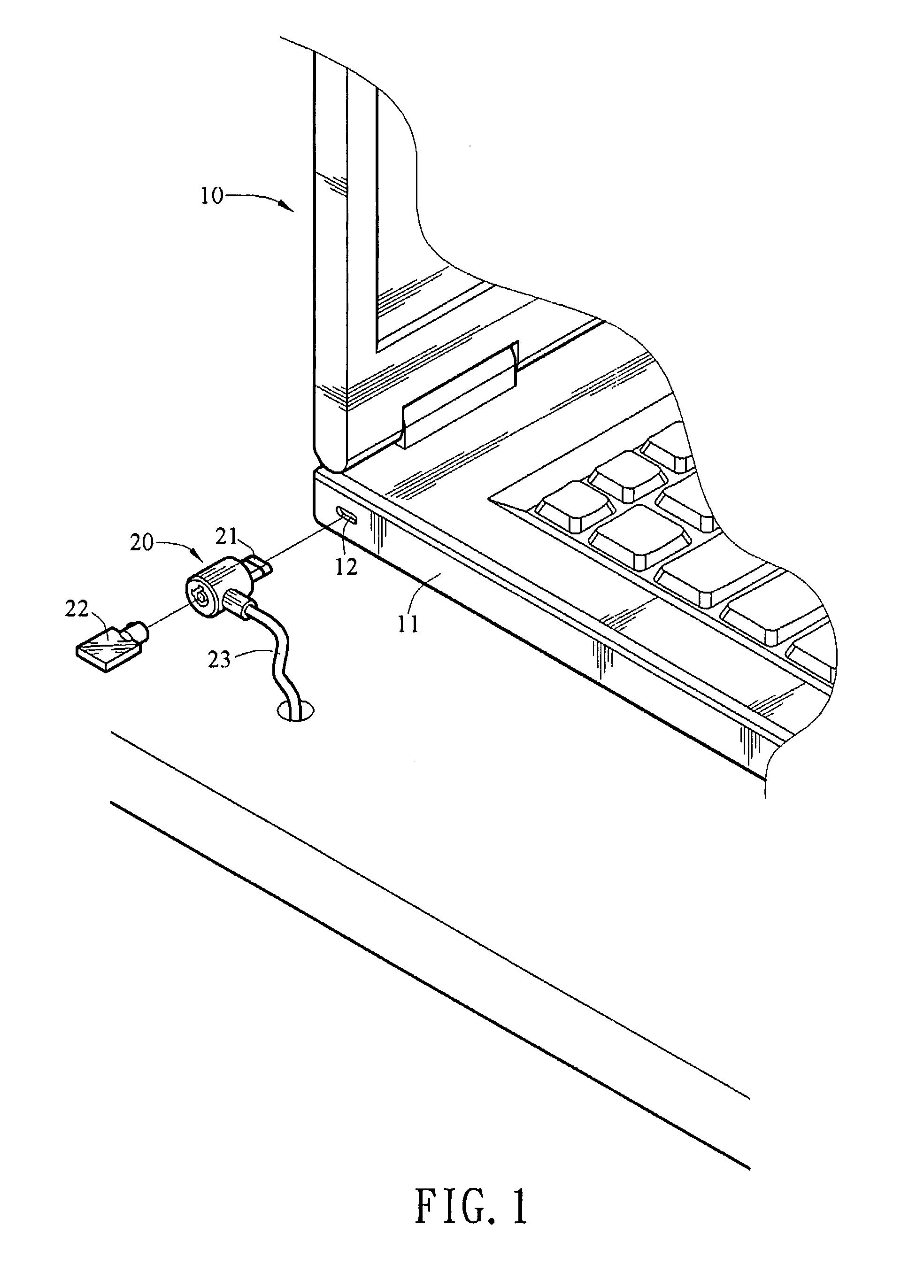
[0023]Referring to FIG. 1, it shows a portable electronic device 10 with an anti-theft lock structure according to a first embodiment of the present invention, which can be locked by a lock 20. The portable electronic device 10 can be, but not limited to, notebook computers, personal digital assistants (PDAs), or portable multimedia players.

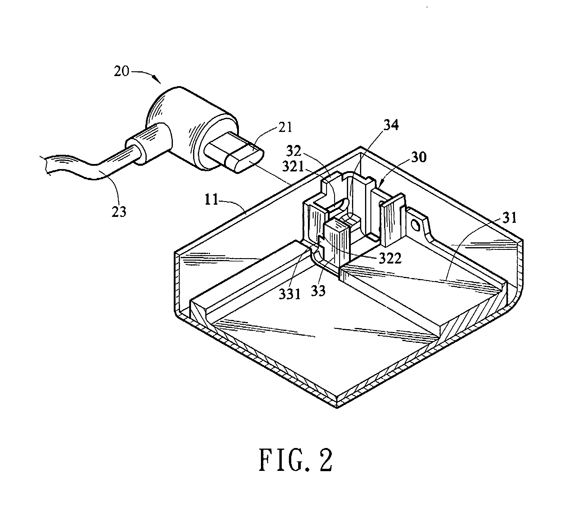
[0024]The portable electronic device 10 has a case 11, for carrying and protecting electronic elements of the portable electronic device 10. An opening 12 is opened in one side of the case 11. A lock tongue 21 is formed at one side of the lock 20 and connected to a lock core (not shown) within the lock 20, such that the lock tongue 21 is rotated upon being driven by the lock core, and thereby being locked at a lock position. The lock tongue 21 is inserted through the opening 12 of the case 11. Once being t...


PUM


Abstract

An anti-theft lock structure including a base, a frame, and a sensor is provided, which is applicable for a lock tongue of a lock to be inserted in. The frame fixed on one side of the base has a lock hole and a stopping portion, wherein the lock hole is engaged with the lock tongue of the lock, and the lock tongue is inserted into the frame through the lock hole. The sensor is fixed in the base and connected to one side of the stopping portion of the frame, for detecting the displacement of the stopping portion relative to the base when the frame is deformed under an external force, so as to generate a trigger signal.

Description

BACKGROUND OF THE INVENTION[0001]1. Field of Invention[0002]The present invention relates to an anti-theft device for an electronic product. More particularly, the present invention relates to a dual anti-theft lock structure for a portable electronic device.[0003]2. Related Art[0004]As the information gradually becomes electronic data, electronic products have already become an indispensable part in people's daily life. In order to enable users to obtain information at any time anywhere, various electronic products are designed towards the trend of portability by individuals, so as to develop different types of portable electronic devices. Take the most common notebook computer as an example, and due to the high mobility, the notebook computer brings a quick pace and convenience to the work of the business people, which thus gradually replaces the leading position of desktop computers in the personal computer (PC) market.[0005]However, in order to match with the portability propert...

Claims


Application Information

Patent Timeline
Patent Type & Authority Applications(United States)
IPC IPC(8): E05B73/00
CPCE05B45/083E05B73/0082E05B73/0005Y10T70/5009
Inventor LIAO, FEI-CHIN
Owner INVENTEC CORP
Learn More