Fixation Device Especially for Glass Folding Devices

a technology of fixing device and glass, which is applied in the direction of door/window fitting, wing fastener, building components, etc., can solve the problems of large size, large visual disturbance of fitting parts projecting past the panel section, and large size of the panel, so as to improve thermal insulation properties, more delicate, and pleasing

Active Publication Date: 2018-06-28
SOLARLUX ALUMINUM SYST
View PDF13 Cites 0 Cited by
  • Summary
  • Abstract
  • Description
  • Claims
  • Application Information

AI Technical Summary

Benefits of technology

[0013]It is particularly advantageous that glass folding devices, comprising panels that are connected to each other to form a chain and can be folded against each other for opening of the folding device, can be designed to be visually more pleasing, more delicate, and with slim frame sections by using the afore described fixation devices. It is thus possible to absorb the weight of the panels by top and bottom supporting and guiding fittings and still secure even long and tall panels across their entire height reliably on each other in that between the supporting and guiding fittings (the conventional hinges) one or a plurality of fixation devices of the afore described kind are employed in the frame sections. When skillfully arranged, the fixation devices preferably can be located completely within a gap between two neighboring panels of the folding device so that they are not visible from the outer side nor from the inner side of the folding device. This makes it also possible to provide neighboring panels with continuous seals on the inner side and outer side between which the fixation device is arranged. Such an arrangement is variable as regards clearance and has continuous sealing planes which improves thermal insulation properties. Also, the fixation devices are not visible for the observer and this not only has visual advantages but also provides improved protection against burglary.

Problems solved by technology

However, the fitting parts which are projecting past the panel sections are perceived as visually disruptive.
Such hinges comprise usually five-axis holding systems, are constructively complex, and have a relatively large size.

Method used


Image

  • Fixation Device Especially for Glass Folding Devices
  • Fixation Device Especially for Glass Folding Devices
  • Fixation Device Especially for Glass Folding Devices

Examples


Embodiment Construction

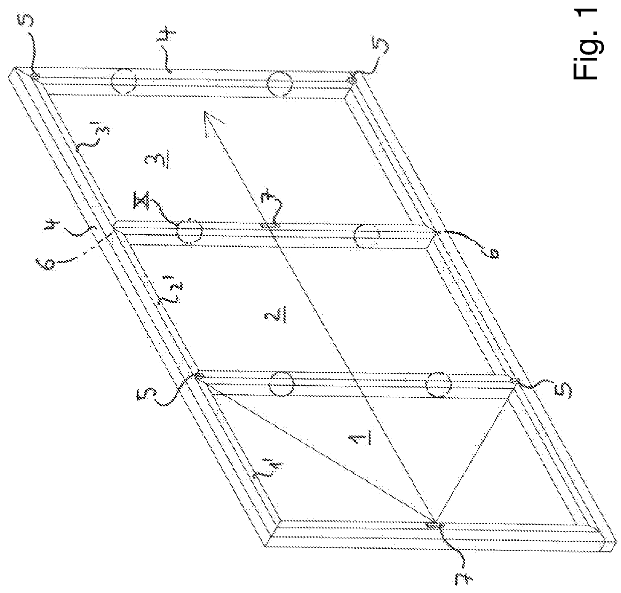
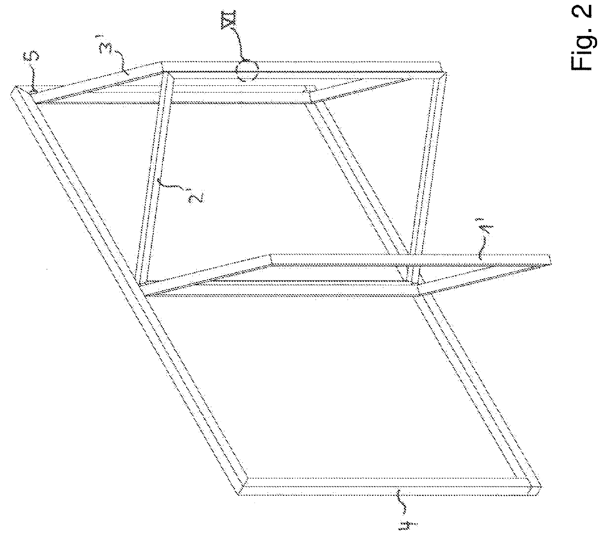
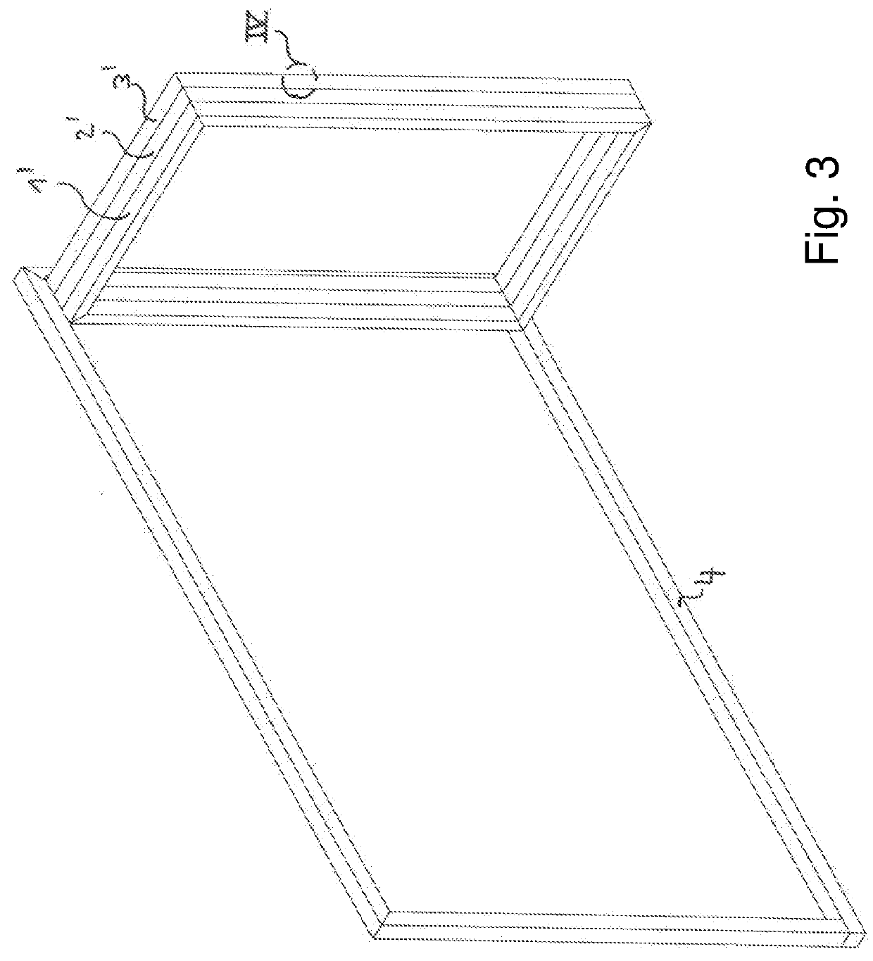
[0026]The folding device illustrated in FIG. 1 comprises a chain of three areal construction components 1, 2, 3 which are embodied here as glass panels with narrow frame sections 1′, 2′, 3′. The panels 1, 2, 3 are guided on an outer frame 4 by means of supporting and guiding fittings 5, 6 in a pivotable and partially slidable way. The inner supporting and guiding fittings 5 are visible in FIG. 1 while the outer supporting and guiding fitting 6 are not visible when viewed from the inner side of the folding device shown in FIG. 1 so that the reference numeral 6 only indicates their position. The folding device comprises locking grips 7. The arrow indicates the opening direction of the folding device. When opening the folding device, the panels 1, 2, 3 move past the position of FIG. 2 to the completely open position of the folding device as shown in FIG. 3. Fixation devices can be located, for example, at the positions indicated by circles and one such fixation device will be explained...


PUM


Abstract

A fixation device for limiting a gap between a first construction component and a second construction component relative to which the first construction component is movable has first and second fitting parts attached to the first and second construction components, respectively. The first fitting part has a fixation projection with first end and opposed second end. The first end is pivotable about a fixation axis fixed at the first construction component. The fixation projection is pretensioned so as to pivot the second end away from the first construction component. The second fitting part has a guiding surface and a holding element. Fixation projection and guiding surface interact such that, when the construction parts are moved toward each other, the second end glides along the guiding surface toward the holding element and catches therein. A folding device of construction components is provided with such fixation devices.

Description

BACKGROUND OF THE INVENTION[0001]The invention relates to a fixation device for movable, areal construction components, such as e.g. windows, doors or glass panels, for delimiting a gap between a narrow side of the areal construction component and a corresponding side of a further construction component, relative to which the areal construction component is movable, wherein the fixation device comprises interacting fitting parts on the narrow side of the areal construction component and on the corresponding side of the further construction component.[0002]The invention further relates to a folding device, in particular a glass folding device, comprising at least a chain of areal construction components that are connected to each other and configured as panels which, for opening the folding device, can be folded against each other, wherein each panel is pivotably connected to the neighboring panel within the chain by top and bottom supporting and guiding fittings arranged on the pane...

Claims


Application Information

Patent Timeline
Patent Type & Authority Applications(United States)
IPC IPC(8): E05C7/06E05C19/02E06B3/50
CPCE05C7/06E05C19/024E06B3/5018E05B65/0085E06B3/481E05D15/26E05Y2900/142
Inventor NIEHAUSMEIER, UWEKLAFFKE, MATTHIAS
Owner SOLARLUX ALUMINUM SYST
Why Eureka
Try Eureka