
LED interconnect spring clip assembly

a technology of interconnection spring and assembly, which is applied in the direction of transportation and packaging, coupling device connection, lighting and heating apparatus, etc., can solve the problems of high die or junction temperature, high heat sinking requirements, and high output led package failures

Inactive Publication Date: 2008-09-18
VARROC LIGHTING SYST SRO
View PDF35 Cites 88 Cited by
  • Summary
  • Abstract
  • Description
  • Claims
  • Application Information

AI Technical Summary

Benefits of technology

[0009]In satisfying the above need, as well as overcoming the enumerated drawbacks and other limitations of the related art, the present invention provides an LED interconnect spring clip assembly including a...

Problems solved by technology

However, one problem with LEDs is that they require adequate heat sinking in order to preserve their long life.
High output LED packages are subject to failure caused by, among other things, localized hotspots and thermal runaway.
A high output LED die is operated with high drive currents resulting in high die or junction temperatures, in the range of 150 degrees Celsius or higher.
When the substrate material reaches a high enough temperature, it expands and causes mechanical stresses in the bonded contact, weakening it.
The reliability of the connections is limited on standard substrates such as FR4 or flexible circuits.
However, these design parameters make the assembly of the LED packages costly.
However, with high die and / or junction temperatures, solder interconnects have proven to be unreliable.

Method used


Image

  • LED interconnect spring clip assembly
  • LED interconnect spring clip assembly
  • LED interconnect spring clip assembly

Examples


Embodiment Construction

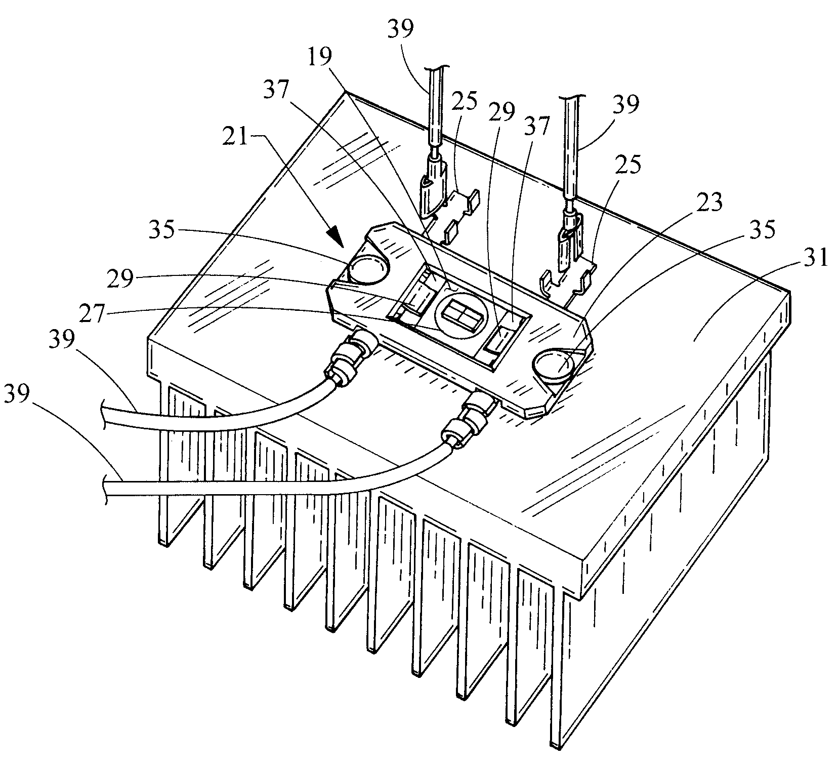
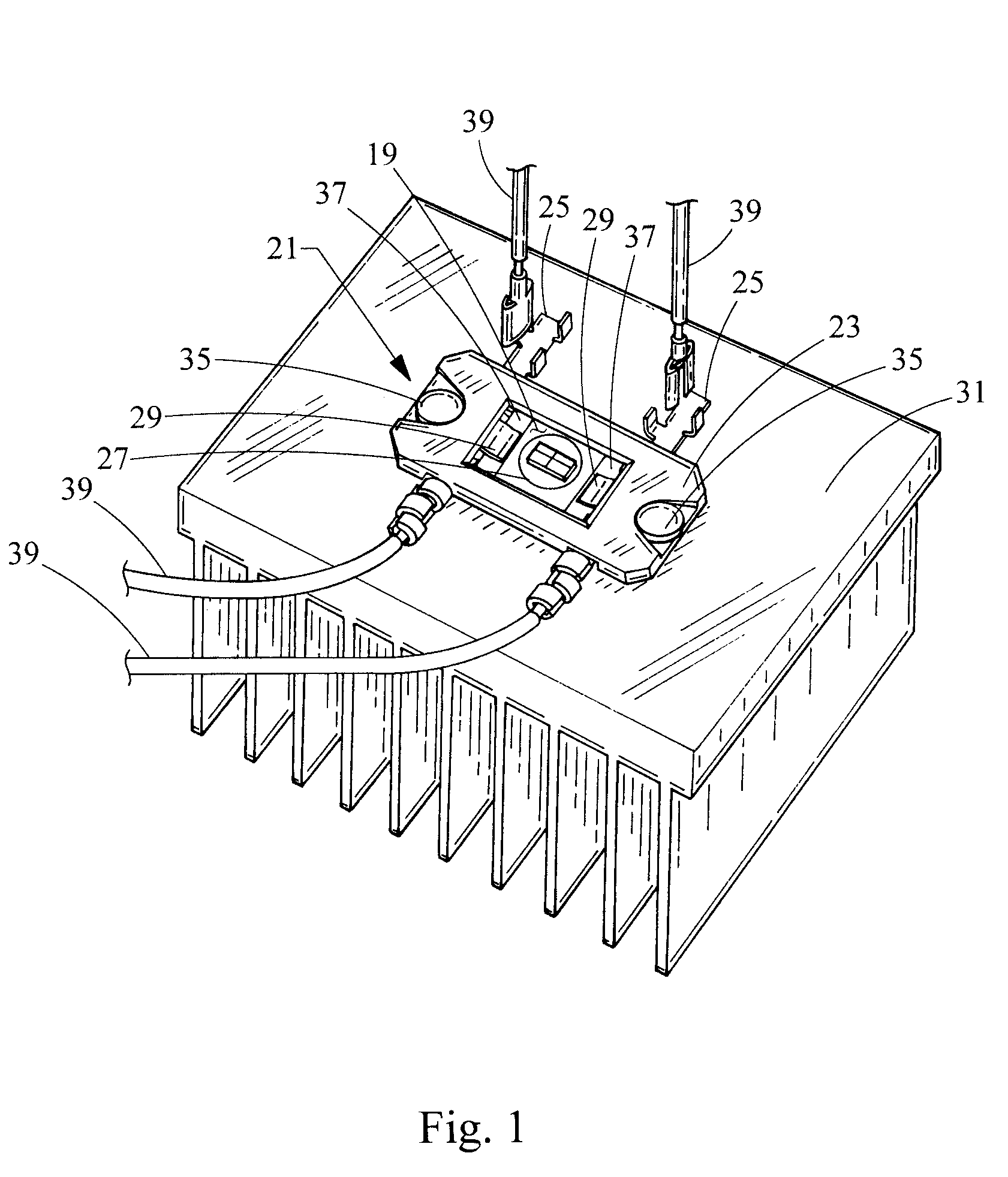
[0027]Referring now to FIG. 1, an LED interconnect spring clip assembly embodying the principles of the present invention is illustrated therein and designated at 21. The LED interconnect spring clip assembly 21 has an electrically insulative housing 23, which retains two contact features, in the form of spring clips 25. Preferably, the spring clips 25 are molded into the housing 23; however, it is also contemplated that the spring clips 25 could be retained by the housing 23 in another way, such as by being snapped into place or otherwise being secured to the housing 23.

[0028]The LED interconnect spring clip assembly 21 has a center cavity 19 formed within the housing 23, in which an LED package 27 may be disposed. The LED package 27 has LED terminals 37, which are electric terminals operable to connect the LED package 27 within a circuit. When the LED interconnect spring clip assembly 21 is fastened to a heat sink 31, by fasteners such as screws 35, the spring clips 25 electricall...


PUM


Abstract

An LED interconnect spring clip assembly includes a housing having a center cavity and a plurality of contact features. Each contact feature has a portion retained by the housing and another portion that is operable to contact a terminal of an LED package disposed within the center cavity of the housing. The LED interconnect spring clip assembly retains the LED package when mounted to a substrate.

Description

BACKGROUND[0001]1. Field of the Invention[0002]The present invention generally relates to light-emitting diode (LED) packaging. More specifically, the invention relates to high output ceramic mounted light-emitting diode (LED) packages for motor vehicle headlamp or other applications.[0003]2. Description of Related Art[0004]An LED is one type of semiconductor that generates light when voltage is applied to it. There are various advantages to using LEDs in vehicle headlamp applications, such as long lifetime, low drive voltage, high vibration resistance, and high tolerance of repeated power switching.[0005]However, one problem with LEDs is that they require adequate heat sinking in order to preserve their long life. High output LED packages are subject to failure caused by, among other things, localized hotspots and thermal runaway. A high output LED die is operated with high drive currents resulting in high die or junction temperatures, in the range of 150 degrees Celsius or higher....

Claims


Application Information

Patent Timeline
IPC IPC(8): H01L33/00
CPCF21S48/115H01R13/24F21V19/004F21V19/0025F21S41/153H01L2224/48091Y10S362/80H01L2924/00014
Inventor GLOVATSKY, ANDREW Z.LIN, JEFF C.
Owner VARROC LIGHTING SYST SRO
Learn More