Demodulation circuit

a demodulation circuit and circuit technology, applied in the field of demodulation circuits, can solve the problems of disabling the demodulation of the ask modulation signal, and achieve the effect of increasing the modulation ratio of the current signal and increasing the modulation ratio

Inactive Publication Date: 2008-09-18
FUJITSU LTD
View PDF1 Cites 6 Cited by
  • Summary
  • Abstract
  • Description
  • Claims
  • Application Information

AI Technical Summary

Problems solved by technology

In this case, however, the range of variation relative to the threshold current IthCOMP also increases in association of increasing the current amplitude of the current ISCOMP, still disabling the demodulation of the ASK modulation signal.

Method used


Image

  • Demodulation circuit
  • Demodulation circuit
  • Demodulation circuit

Examples


Embodiment Construction

[0045]The following is a description of the preferred embodiment of the present invention by referring to the accompanying drawings.

[0046]First is a description of FIG. 5 which is a diagram showing the configuration of a radio frequency identification (RFID) tag which is a noncontact data carrier comprising a demodulation circuit embodying the present invention.

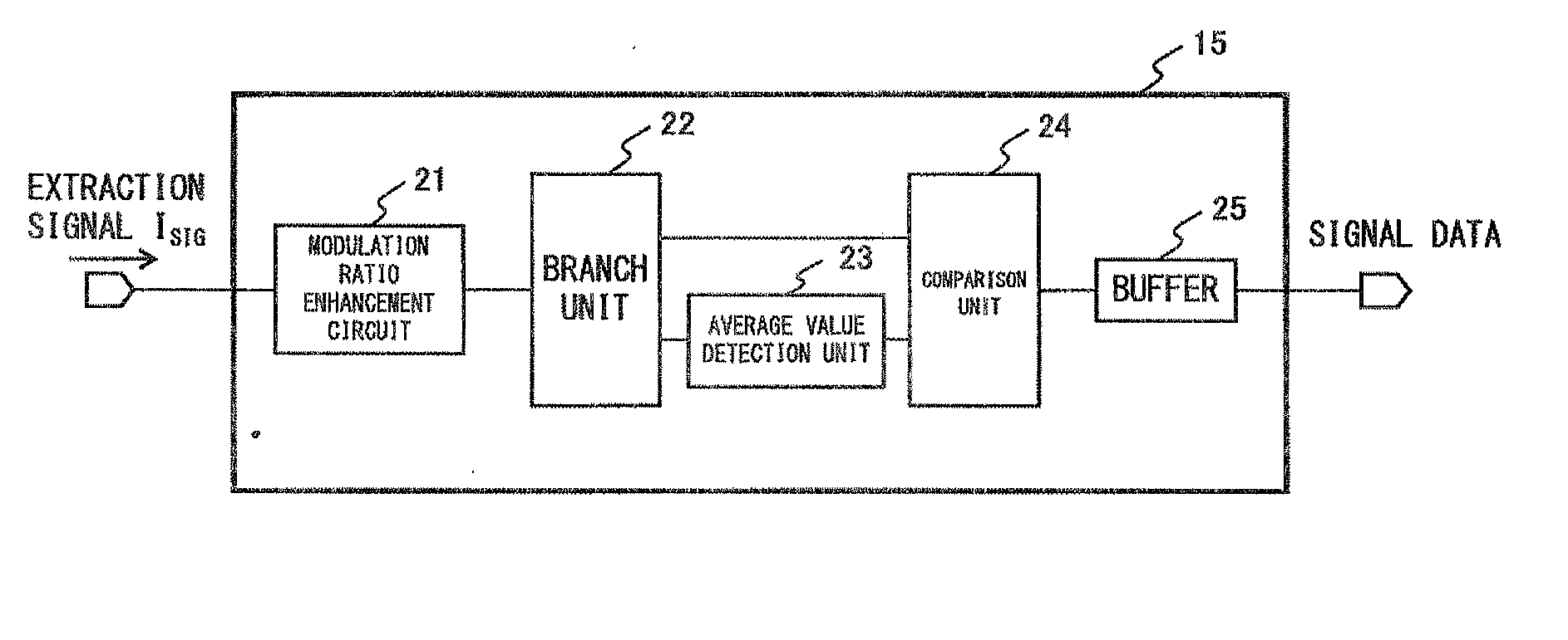
[0047]The RFID tag comprises an antenna unit 11, a rectification circuit 12, a charge capacitor C10, a shunt regulator 13, a signal extraction circuit 14, a demodulation circuit 15, a digital signal process unit 16 and a modulation circuit 17.

[0048]A signal received by the antenna unit 11 is rectified by the rectification circuit 12, followed by being charged in the charge capacitor C10 and turned into the power supply for the digital signal process unit 16. The shunt regulator 13 controls a short-circuit current volume in order to maintain the voltage of the power supply at constant.

[0049]The signal extraction circuit 14 ext...


PUM


Abstract

A modulation ratio enhancement circuit increases the modulation ratio of a current signal which is ASK-modulated with signal data. A branch unit, an average value detection unit, a comparator and a buffer constitute a demodulation unit so that the signal data is demodulated from a current signal of which the modulation ratio is increased by the modulation ratio enhancement circuit.

Description

CROSS REFERENCE TO RELATED APPLICATION[0001]This application is a continuation application of international PCT application No. PCT / JP2005 / 021990 filed on Nov. 30, 2005.BACKGROUND OF THE INVENTION[0002]1. Field of the Invention[0003]The present invention relates to a technique for obtaining original signal data by demodulating a signal which is modulated by signal data, and in particular to a technique suitably applicable to an apparatus.[0004]2. Description of the Related Art[0005]As an example, a technique for obtaining original signal data by comparing the magnitude of an original modulation signal with that of the threshold value generated from the average value of a modulation signal is known as a technique for demodulating a modulation signal which is ASK (Amplitude Shift Keying)-modulated by signal data.[0006]FIG. 1 is a block diagram showing the configuration of a conventional demodulation circuit for demodulating an ASK modulation signal.[0007]In the reception unit 100 show...

Claims


Application Information

Patent Timeline
Patent Type & Authority Applications(United States)
IPC IPC(8): H03D1/00
CPCH04B1/707H04B2201/70715H03D1/22H04L27/06H04L25/067
Inventor YAMAZAKI, DAISUKEGOTOH, KUNIHIKO
Owner FUJITSU LTD
Why Eureka
Try Eureka