Locking Assembly
- Summary
- Abstract
- Description
- Claims
- Application Information
AI Technical Summary
Benefits of technology
Problems solved by technology
Method used
Image
Examples
Embodiment Construction
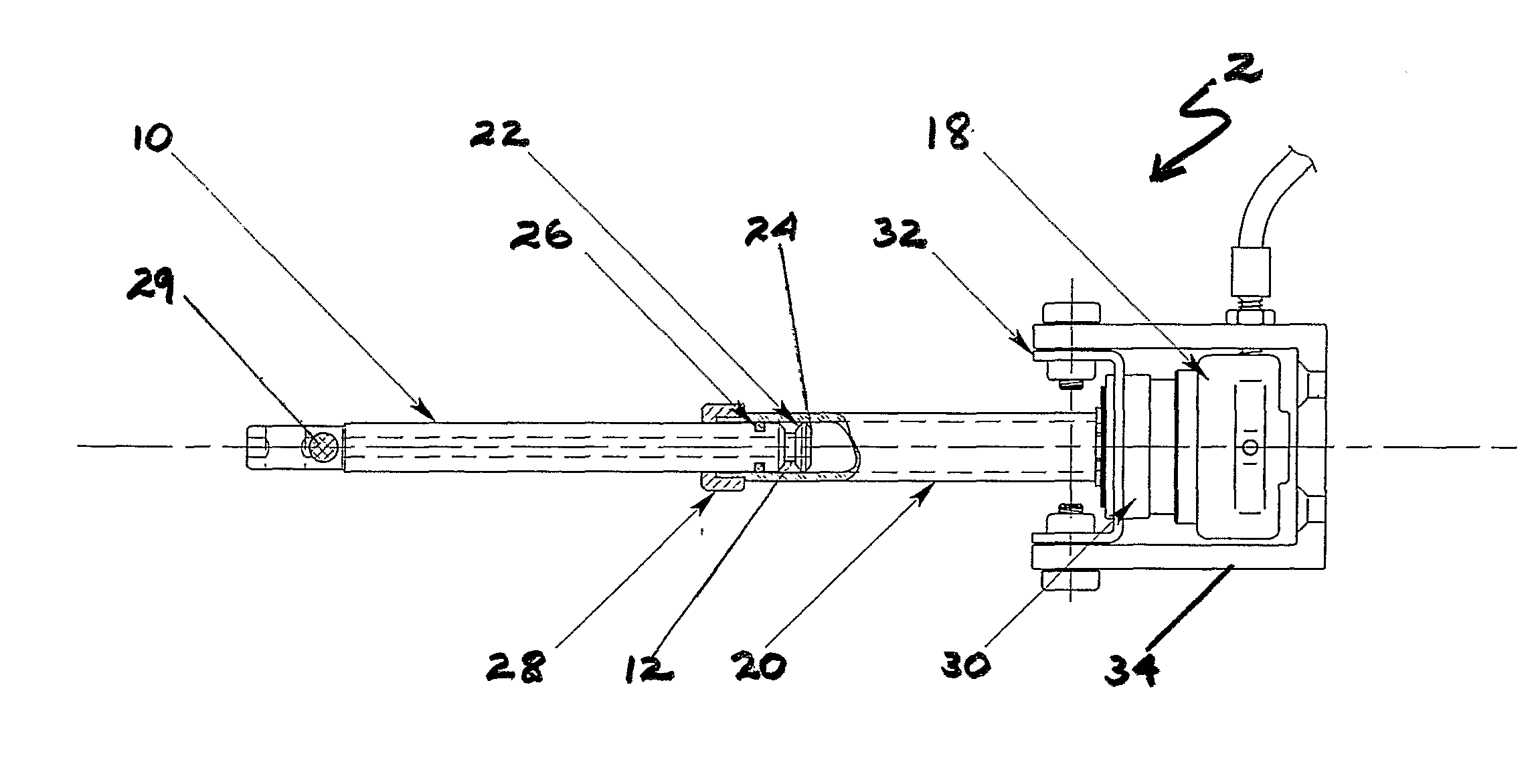
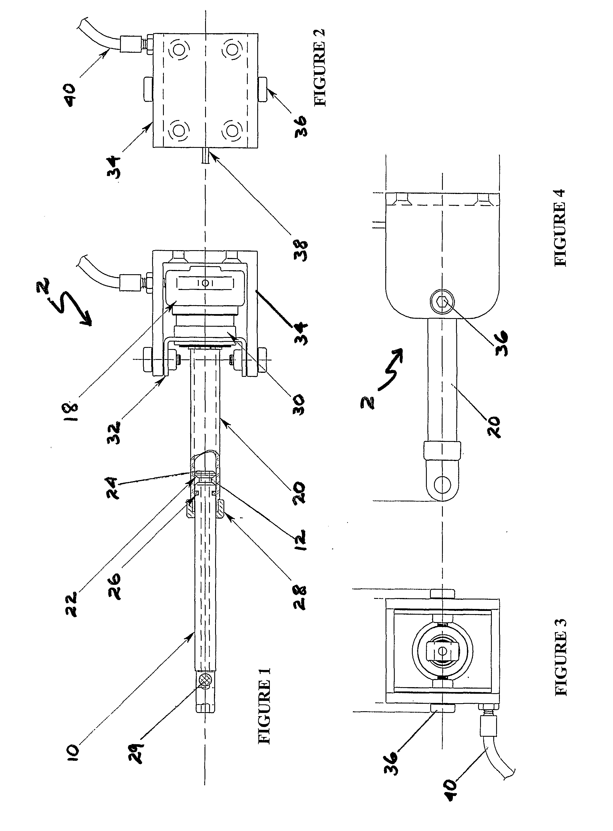
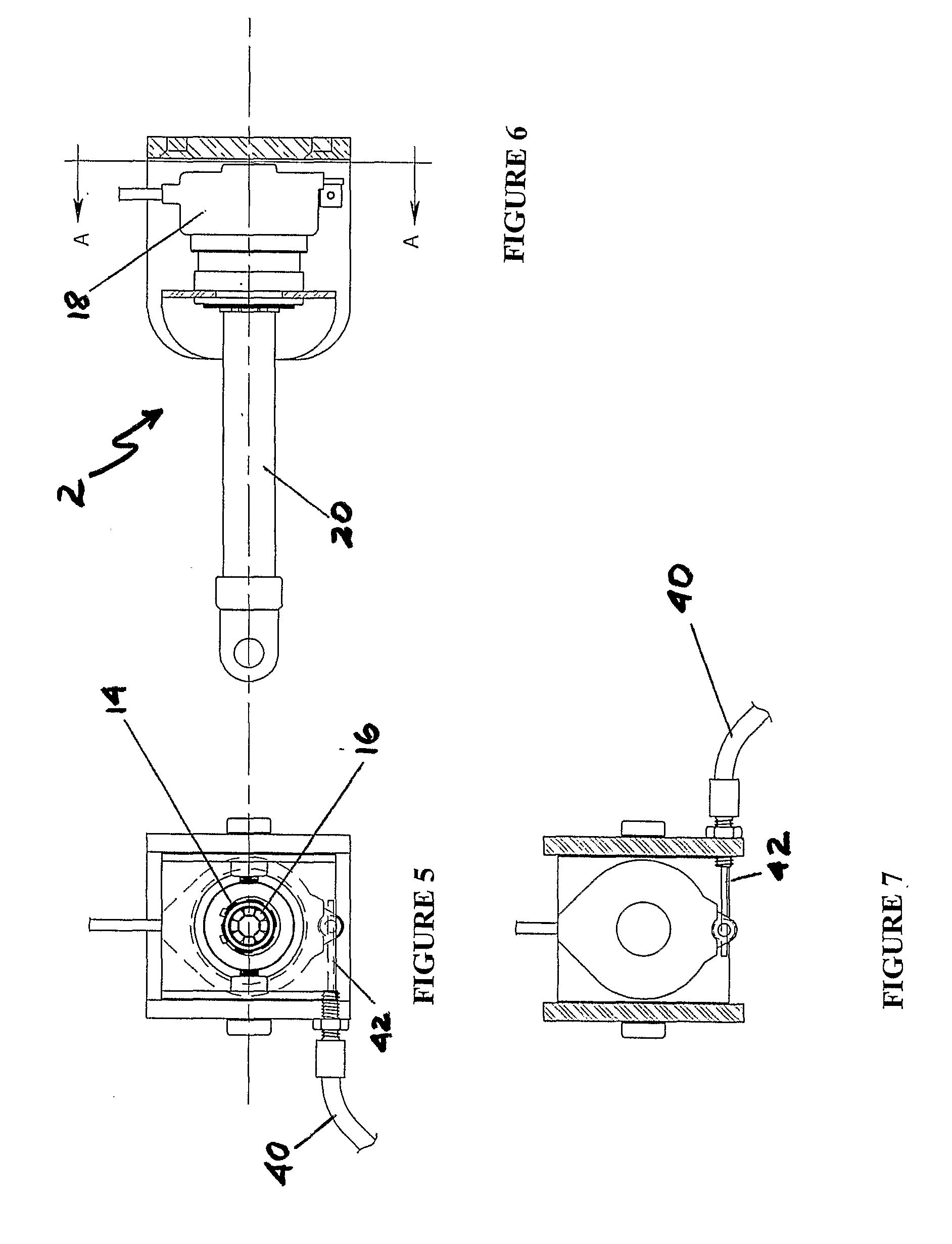
[0077]This invention in the embodiment in FIGS. 1 to 7 features a locking assembly 2 for locking or unlocking a passenger seat. Referring to FIG. 1, locking assembly 2 has a locking stud 10 having a locking cavity, namely groove 12 around its perimeter. Groove 12 has tapered walls, one of which is shown at 22. Locking stud 10 also tapers towards base 24.
[0078]Aperture 14 in body 18 is designed to receive locking stud 10 (Refer FIG. 5).
[0079]Included in body 18 is a rotatable shuttle (not visible but illustrated in imported specification WO 2005 / 047714, together with shape memory alloy wire wound around the shuttle). Also included in body 18 are teeth 16 (FIG. 5) designed to enter groove 12 to lock locking stud 10, as described in the imported specification.
[0080]Locking stud 10 is slidable within locking stud guide 20 (FIGS. 1, 4 and 6). Seal 26, made of rubber, nylon or other suitable material, ensures that locking stud 10 slides in a sealing relationship with the inner walls of gu...
PUM
 Abstract
Description
Claims
Application Information
 - R&D
- Intellectual Property
- Life Sciences
- Materials
- Tech Scout
- Unparalleled Data Quality
- Higher Quality Content
- 60% Fewer Hallucinations
Browse by: Latest US Patents, China's latest patents, Technical Efficacy Thesaurus, Application Domain, Technology Topic, Popular Technical Reports.
© 2025 PatSnap. All rights reserved.Legal|Privacy policy|Modern Slavery Act Transparency Statement|Sitemap|About US| Contact US: help@patsnap.com


