
Spinal Core Platform

a platform and spine technology, applied in the field of exercise, can solve the problems of insufficient adjustment of the device, the inability to fully adjust the device, and the inconvenient use of the devi

Inactive Publication Date: 2008-09-18
BARNIAK CARL
View PDF12 Cites 20 Cited by
  • Summary
  • Abstract
  • Description
  • Claims
  • Application Information

AI Technical Summary

Benefits of technology

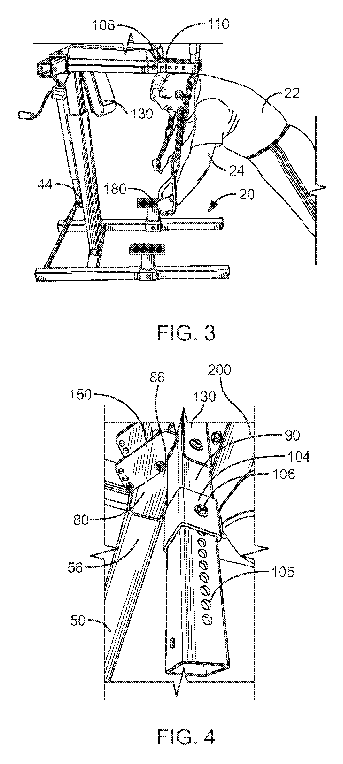
[0018]FIG. 4 is a partial view of the invention, illustrating in more detail a support frame attachment means and a support arm adjustment means;
[0019]FIG. 5 is a partial view of the invention, illustrating in more detail a hand grip member adjustably fixed within a handgrip receiver;
[0020]FIG. 6 is a partial view of the invention, illustrating in ...

Problems solved by technology

Thus, people with body dimensions that do not conform well to such a device may find using such a device uncomfortable.
However, exercise devices in the prior art that accommodate such exercises typically have significant drawbacks.
Principally, such exercise devices do not focus on exercises used for spinal decompression and core conditioning, and thus multiple exercise devices are necessary in physical therapy offices that are often already too crowded.
Further, to the extent that such prior art devices accommodate such exercise therapies, the devices are not fully adjustable.
Often those who are undergoing such physical therapy have non-average body dimensions, and as such a one-size-fits-all exercise machine is not comfortably or profitably used.

Method used


Image

  • Spinal Core Platform
  • Spinal Core Platform
  • Spinal Core Platform

Examples


Embodiment Construction

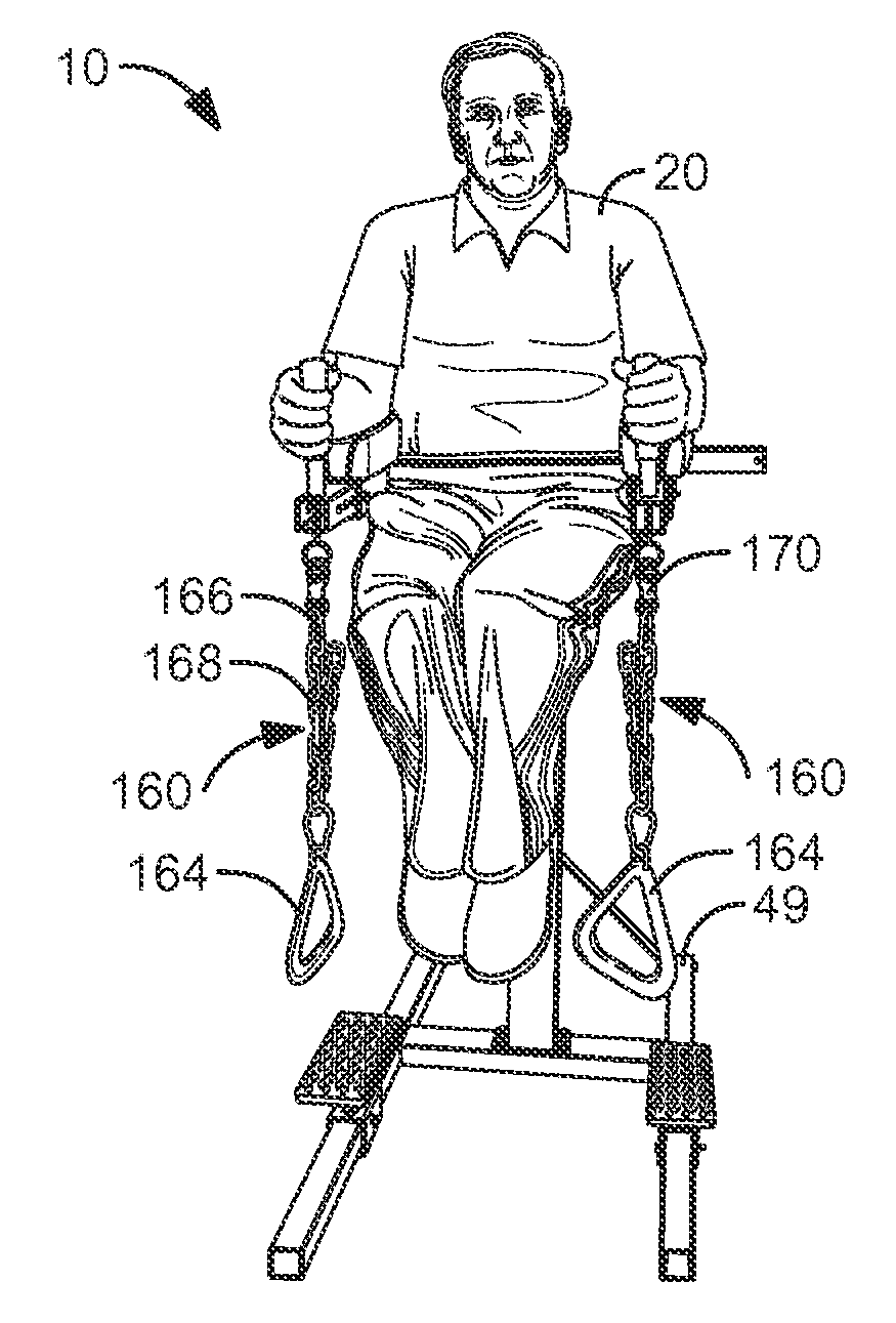
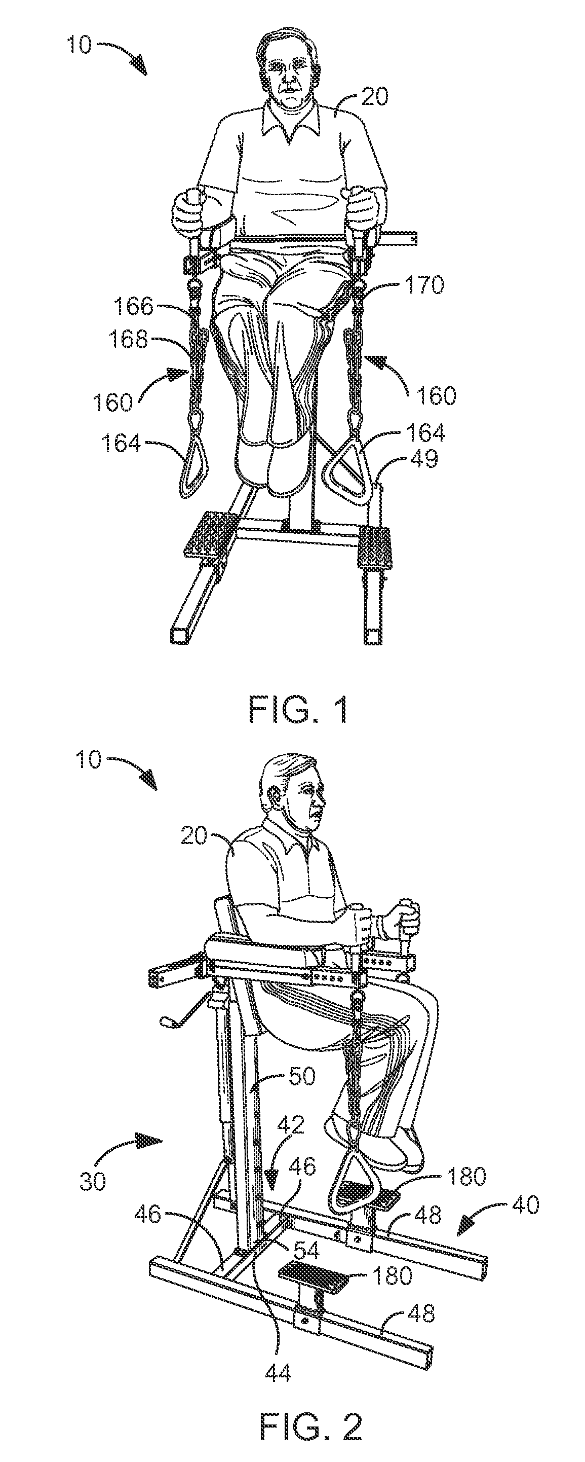
[0025]FIGS. 1 and 2 illustrate a freestanding exercise device 10 for a person 20. A stand 30 includes a substantially horizontal base 40 that is rigidly fixed to a lower end 54 of an upright support member 50. An upper end 56 of the upright support member 50 includes a support frame attachment means 60 (FIGS. 4 and 7). The base 40 preferably includes a generally H-shaped base frame 42 having an elongated base member 44 having two ends 46, each end 46 being fixed generally perpendicularly to an elongated base leg 48 (FIGS. 2 and 9). The horizontal base 40 and upright support member 50 are preferably made for a rigid metal non-circular cross-section stock material, such as from a steel or iron substantially square cross-sectional stock material.

[0026]In the simplest embodiments of the invention, illustrated in FIGS. 1-3, a pair of footrests 180 are included, each adjustably fixed to one of the base legs 48 such as by a sliding sleeve and bolt as shown in FIGS. 2 and 3. As such, the pe...


PUM


Abstract

A freestanding exercise device for a person is disclosed. A stand adjustably supports a generally U-shaped support frame that includes a back rest and a pair of support arms that each terminate in an adjustable hand grip member from which a plurality of ring assemblies are suspended. A pair of footrests are adjustably fixed to base. A high-station assembly includes a high station support member fixed to the stand. A lateral support and a traction bar support arm are fixed to the high station support member, and a traction bar is fixed to the traction bar support arm. The lateral support is fixed at either end thereof to a ring support arm from each of which one ring assembly is suspended. In use, the person may adjust the height of the support frame and the back rest support, and then position himself within the exercise device by resting his back against the back rest, resting his arms on the support arms, gripping the hand grip members, and then performing leg lift exercises. Each support arm is preferably adjustably fixed with a support arm adjustment means, such that the person may additionally adjust the distance between the support arms. The person may use the lower suspended ring assemblies to perform push-up type exercises, or, alternately, he may grasp each ring of the high-station assembly to perform pull-up and related exercises. The person may grasp the traction bar and hang therefrom to create traction forces within the person's back.

Description

CROSS-REFERENCE TO RELATED APPLICATIONS[0001]Not Applicable.STATEMENT REGARDING FEDERALLY SPONSORED RESEARCH AND DEVELOPMENT[0002]Not Applicable.FIELD OF THE INVENTION[0003]This invention relates to exercise, and more particularly to an improved spinal decompression and core conditioning exercise and therapy device.DISCUSSION OF RELATED ART[0004]Exercise devices of the type resembling leg-lift chairs are known in the prior art. For example, U.S. Pat. No. 5,302,164 to Austin on Apr. 12, 1994, teaches such a device for mounting into the corner of a room. Some aspects of this type of device are adjustable, but not the distance between the arm supports. Thus, people with body dimensions that do not conform well to such a device may find using such a device uncomfortable.[0005]Similarly, U.S. Pat. No. 6,712,744 to Buechel, Jr. et al., on Mar. 30, 2004, teaches an exercise device having push-up bars. The distance between the bars is not adjustable in this device, although the height of th...

Claims


Application Information

Patent Timeline
IPC IPC(8): A63B26/00
CPCA63B3/00A63B21/0442A63B21/068A63B2225/093A63B23/1236A63B2208/0204A63B2208/029A63B23/0216
Inventor BARNIAK, CARL
Owner BARNIAK CARL
Learn More