Unlock instant, AI-driven research and patent intelligence for your innovation.
Power management topologies
What is Al technical title?
Al technical title is built by PatSnap Al team. It summarizes the technical point description of the patent document.
a topology and power management technology, applied in the field of power management systems, can solve the problems of increasing the cost of the power supply system, unusable inter-current flow from the higher voltage source, and the inability to charge the battery output voltag
Inactive Publication Date: 2008-09-25
O2 MICRO INT LTD
View PDF4 Cites 22 Cited by
Summary
Abstract
Description
Claims
Application Information
AI Technical Summary
This helps you quickly interpret patents by identifying the three key elements:
Problems solved by technology
Method used
Benefits of technology
Problems solved by technology
Since the output voltage of the ACDC adapter has a fixed value while the output voltage of the battery may vary largely (depending on its charged state) the ACDC adapter and the battery can not be coupled in parallel to supply power to the system load at certain times. This difference in voltage would lead to undesirable inter-current flow from the higher voltage source (ACDC adapter) to the lower voltage source (battery).
As a result, in order to account for transient high power needs of the system, the ACDC adapter is typically oversized, significantly increasing the cost of the power supply system.
In addition, since the ACDC adapter's output voltage is fixed, its output voltage cannot be used to charge the battery which entails fine charging voltage and current control.
This second power conversion step causes further cost increase and diminishes the overall efficiency of the power supply system.
Method used
Image
Click on the blue label to locate the original text in one second.
Reading with bidirectional positioning of images and text.
Examples
Embodiment Construction
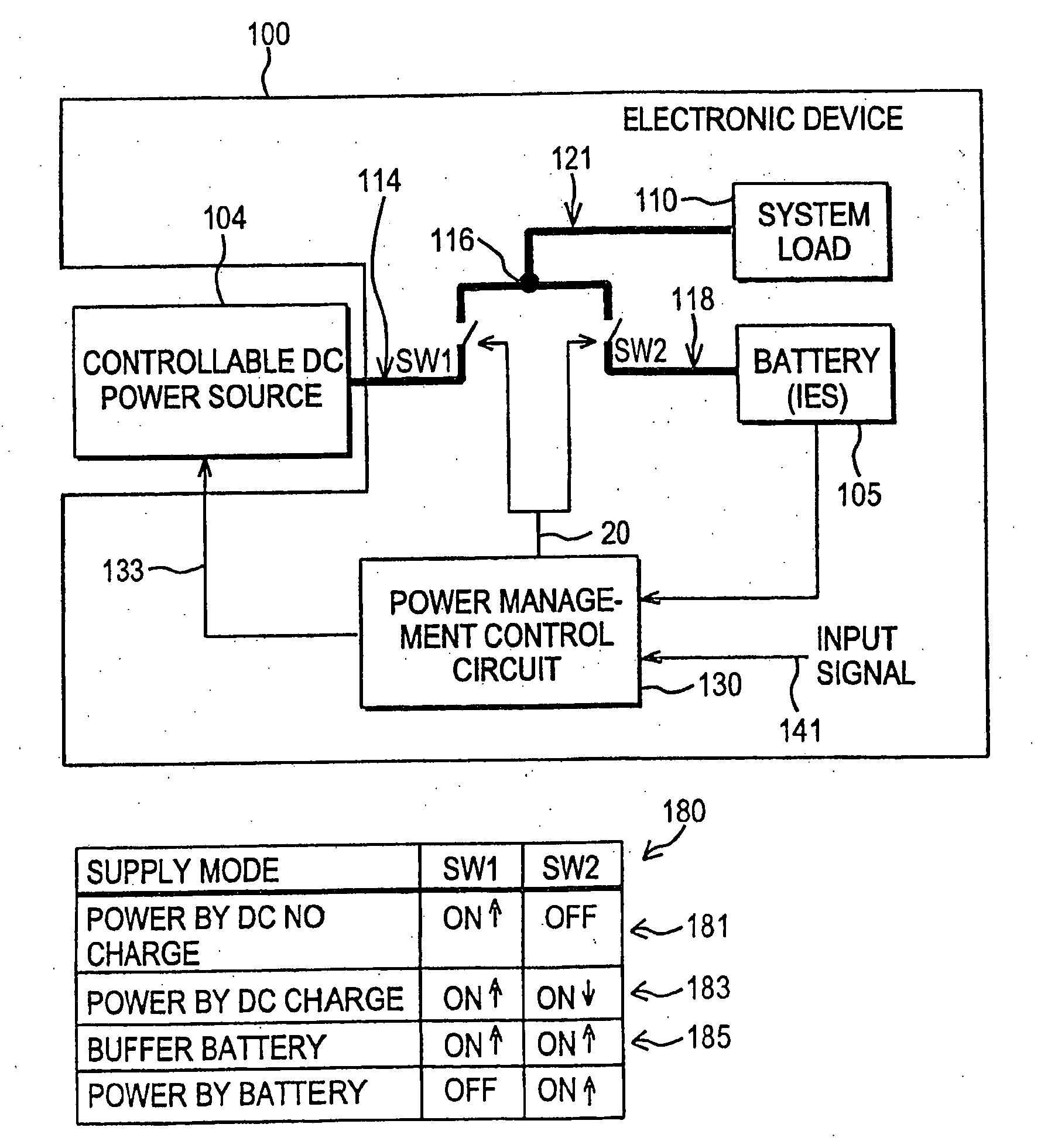
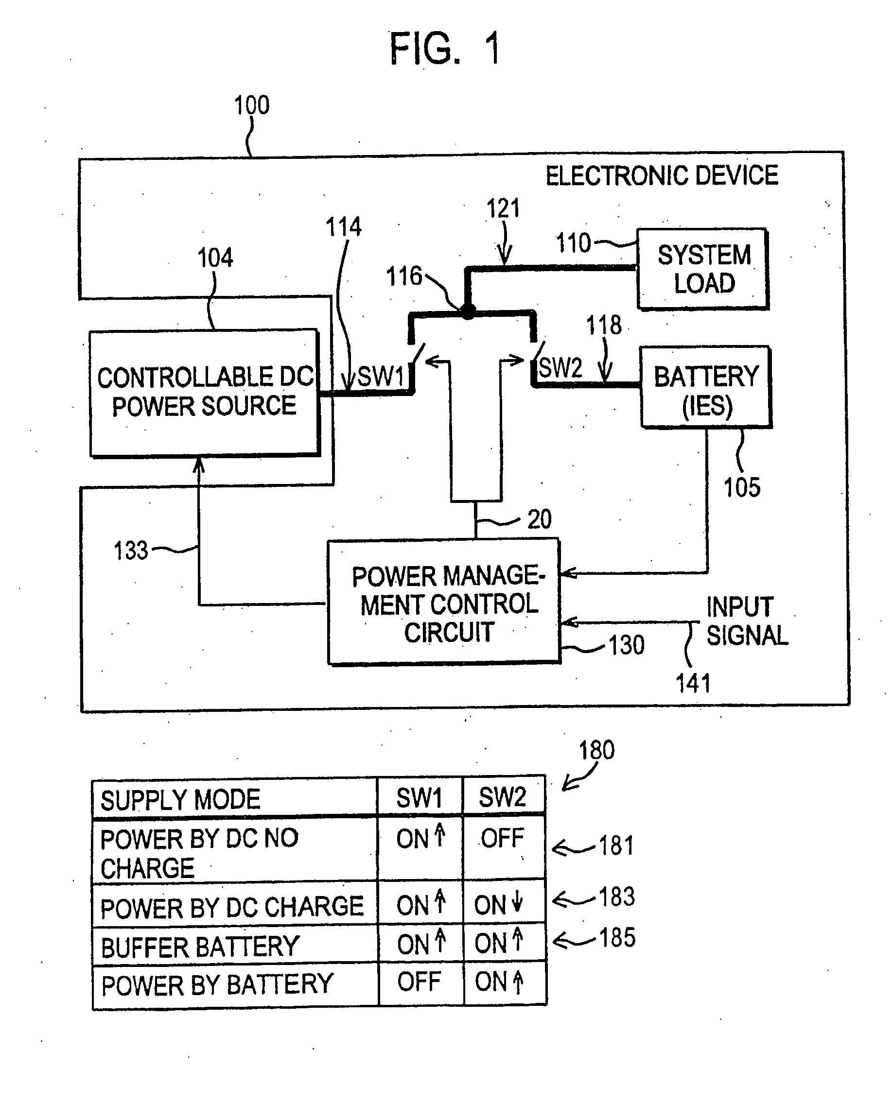
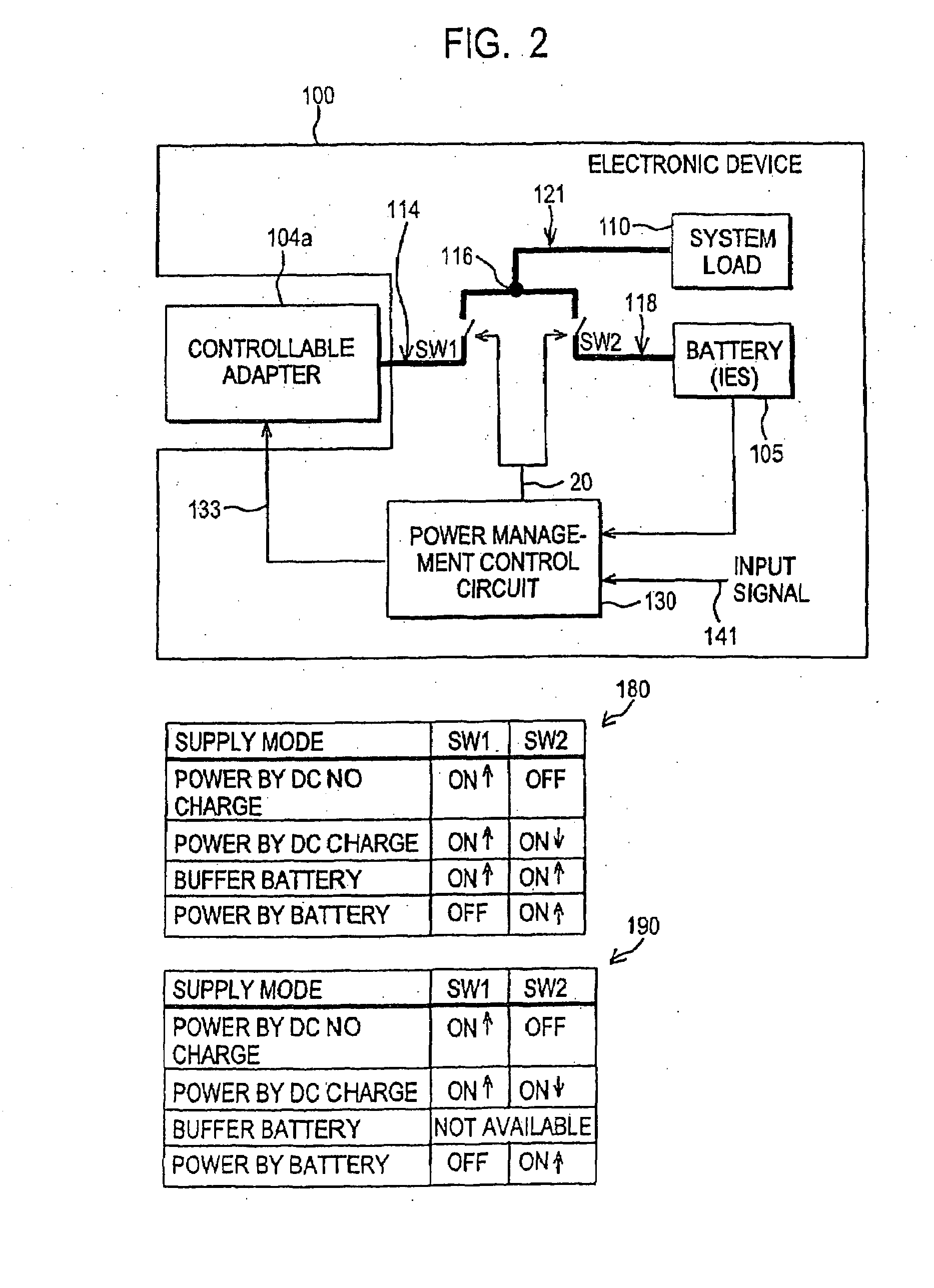
[0026]FIG. 1 illustrates a simplified block diagram of an electronic device 100 having a system load 110 capable of being powered by a controllable DC power source 104, a battery 105, or by both in parallel as the need arises as further detailed herein. A table 180 showing the position of switches SW1 and SW2 in various power supply modes is also illustrated. In one embodiment, the controllable DC power source 104 may be a controllable adapter as further detailed herein, e.g., an ACDC adapter, that provides the only power conversion necessary to deliver power to the system load 110 and the battery 105. As such, the need for an additional power conversion step (e.g., a DC to DC converter to provide a finely controlled output to the battery for charging) typically utilized in other power supply systems is obviated in this instance.
[0027]The electronic device 100 may be any variety of devices known in the art such as a laptop computer, cell phone, personal digital assistant, power tool...
PUM
Abstract
A power supply topology according to one embodiment includes a first path coupled to a controllable DC power source, a second path coupled to a rechargeable battery, and a third path coupled to a system load, the three paths coupled to a common node. The topology may further include a unidirectional switch coupled to the first path and a selectively unidirectional switch coupled to the second path. The topology may further include a power management control circuit including a wake up circuit having a comparison circuit and an output decision circuit. Of course, many alternatives, variations, and modifications are possible without departing from this embodiment.
Description
CROSS REFERENCE TO RELATED APPLICATIONS[0001]This application is a continuation of U.S. Nonprovisional application Ser. No. 10 / 812,802 filed Mar. 30, 2004, now U.S. Pat. No. 7,348,760, which itself is a continuation-in-part application of U.S. Nonprovisional application Ser. No. 10 / 652,110 filed Aug. 29, 2003, which itself is a continuation-in-part application of U.S. Nonprovisional application Ser. No. 10 / 364,228 filed Feb. 11, 2003, now U.S. Pat. No. 6,977,482, the teachings of which are incorporated herein by reference, and claims the benefit of the filing date of U.S. Provisional Application Ser. No. 60 / 484,635, filed Jul. 3, 2003, the teachings of which are also incorporated herein by reference. U.S. Nonprovisional application Ser. No. 10 / 652,110 filed Aug. 29, 2003 is also a continuation-in-part of U.S. Nonprovisional application Ser. No. 09 / 960,453 filed Sep. 21, 2001, now U.S. Pat. No. 6,741,006, the teachings of which are incorporated herein by reference, and claims the ben...
Claims
Application Information
Patent Timeline
Application Date:The date an application was filed.
Publication Date:The date a patent or application was officially published.
First Publication Date:The earliest publication date of a patent with the same application number.
Issue Date:Publication date of the patent grant document.
PCT Entry Date:The Entry date of PCT National Phase.
Estimated Expiry Date:The statutory expiry date of a patent right according to the Patent Law, and it is the longest term of protection that the patent right can achieve without the termination of the patent right due to other reasons(Term extension factor has been taken into account ).
Invalid Date:Actual expiry date is based on effective date or publication date of legal transaction data of invalid patent.
Patent Type & Authority Applications(United States)

