Power buffer design method based on model predictive control

A technology of model predictive control and design method, applied in simulators, general control systems, control/regulation systems, etc., can solve problems such as high model accuracy requirements, meet power quality requirements, and achieve energy optimal distribution.

Active Publication Date: 2019-05-10
NORTHWESTERN POLYTECHNICAL UNIV
View PDF13 Cites 6 Cited by
  • Summary
  • Abstract
  • Description
  • Claims
  • Application Information

AI Technical Summary

Problems solved by technology

However, the algorithm has high requirements for the accuracy of the model, especially the demand for load needs to be accurately observed

Method used


Image

  • Power buffer design method based on model predictive control
  • Power buffer design method based on model predictive control
  • Power buffer design method based on model predictive control

Examples


Embodiment Construction

[0031]This embodiment is a method for designing a power buffer based on model predictive control.

[0032] The technical features involved in this embodiment described below may be combined as long as they do not constitute a conflict with each other.

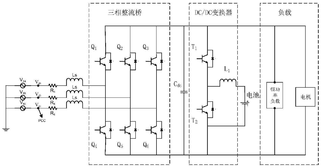
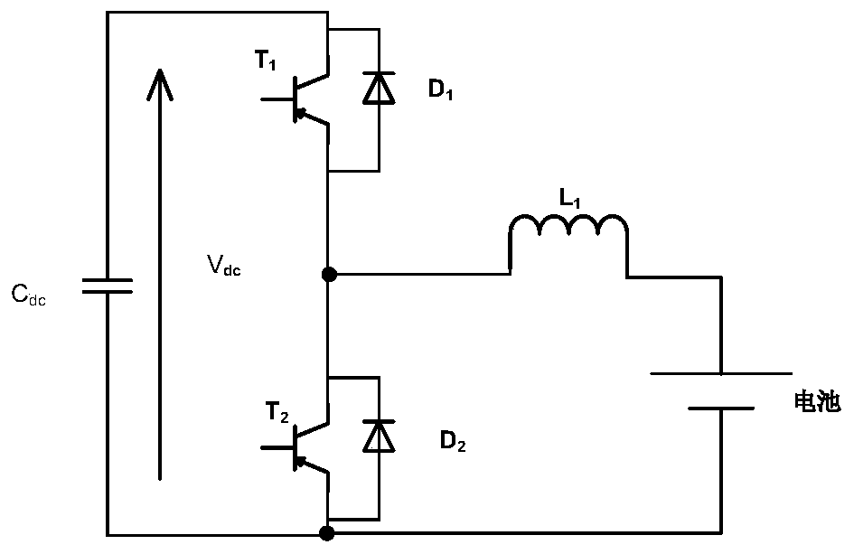
[0033] See attached figure 1 , the topology of the power buffer converter refers to the attached figure 1 . where v sa , v sb , v sc Represents a three-phase power supply; R s is the equivalent line resistance of the AC side; L s is the AC side inductance; the switching tube Q 1 ~Q 6 A three-phase rectifier bridge is formed; C dc is the DC side capacitance; the switching tube T 1 , T 2 and inductance L b A DC / DC converter is formed; the energy storage element is a battery or a super capacitor; the latter stage is a constant power load and a motor load.

[0034] This embodiment is verified by MATLAB / Simulink simulation. The specific implementation steps are as follows:

[0035] Step 1. Build a simulation model in ...


PUM


Abstract

The invention discloses a power buffer design method based on model predictive control. By utilizing a characteristic of multi-objective optimization of the model predictive control, a three-phase rectifier bridge and a DC/DC converter are controlled at the same time. A target optimization function is designed by adopting a finite set method; in combination with constraint conditions of differentenergy flow coupling, an overall control model is built; multi-objective optimization control can be realized by adopting the model predictive control method; and for a power supply system with an energy storage device, an active energy management mode is adopted, so that the energy optimization distribution of a more electric aircraft can be realized. Therefore, direct-current bus voltage is stable. The model performs buck-boost control on the bidirectional DC/DC converter according to the energy feedback condition of a motor, and direct-current bus power is stable through charging and discharging of a battery pack. The power topology of the power buffer converter is adopted; and the direct current bus power is compensated and absorbed through a storage battery, so that the weight of theaircraft can be effectively reduced.

Description

technical field [0001] The invention relates to a power buffer converter voltage stabilization and energy storage control method with an energy feedback motor and a constant power load in a multi-electric aircraft electrical system. Background technique [0002] In recent years, with the introduction of multi-electric and all-electric aircraft, distributed power distribution technology has been widely used in independent power systems such as multi-electric and all-electric aircraft in the future. According to some data, the constant power load can account for 80% of the total load in the high-voltage DC power distribution system of multi-electric and all-electric aircraft in the future. The proportion of constant power loads in the system is increasing, and the problems it brings are becoming more and more prominent. [0003] For a constant power load, although its instantaneous impedance is positive But its corresponding impedance increment is negative This characteri...

Claims


Application Information

Patent Timeline
Patent Type & Authority Applications(China)
IPC IPC(8): G05B17/02H02J7/34
Inventor 雷涛陈光巳刘晓飞张晓斌
Owner NORTHWESTERN POLYTECHNICAL UNIV
Why Eureka
Try Eureka