Coating power supply system and coating device comprising same
A power system and circuit technology, applied in the power supply field, can solve the problems of inability to realize input and output applications, difficult to meet power quality requirements, and inability to output square wave pulses, so as to improve stability and safety, prevent pulse mutation, and reduce dynamic The effect of fluctuations
- Summary
- Abstract
- Description
- Claims
- Application Information
AI Technical Summary
Problems solved by technology
Method used
Image
Examples
Embodiment 1
[0080] The conventional power supply system generally adopts AC rectification and performs one-stage DC-DC isolation voltage regulation pulse output, which is difficult to achieve a wide range of input and output applications, and the output pulse waveform is mostly sine wave, and the square wave pulse power supply is less, which is difficult to meet Power supply quality requirements in application fields such as photovoltaic coating and semiconductor coating can easily cause damage to back-end equipment and affect production efficiency. The existing technology does not optimize the power system, cannot realize a wide range of input and output applications, cannot output square wave pulses suitable for photovoltaic coating, semiconductor coating and other application fields, and is difficult to meet the power quality requirements of application scenarios with high power performance requirements.
[0081] In view of the above problems, the embodiment of the present application p...
Embodiment 2
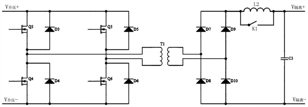
[0090] For ease of understanding, an example of a coating power supply system is provided below for illustration. In practical applications, the boost DCDC circuit will use a MOS boost circuit, and the isolated DCDC circuit will use a bridge converter. When the pulse generating circuit is a ladder When the wave generating circuit is used, the bridge inverter circuit can use a three-level H-bridge circuit to output a ladder wave according to the driving sequence to meet the demand for high-quality square wave pulses in photovoltaic coating, semiconductor coating and other application fields.
[0091] see Figure 2 to Figure 5 , Embodiment 2 of the coating power supply system shown in the embodiment of the present application includes:
[0092] Such as figure 2 As shown, the step-up DCDC circuit is a MOS step-up circuit, that is, a MOS tube step-up circuit, and the MOS tube refers to a field effect tube. Specifically, the MOS boost circuit includes a capacitor C1, an inductor...
Embodiment 3
[0106] For ease of understanding, an embodiment of the coating power supply system is provided below for illustration. In practical applications, after the treatment of the isolated DCDC circuit, the voltage regulating DCDC circuit will be further designed, and the H bridge circuit will be used to output T Type wave to meet the needs of more application scenarios.
[0107] see Figure 6 and Figure 7 , the third embodiment of the coating power system shown in the embodiment of the present application includes:
[0108] When the pulse generating circuit is a T-shaped wave generating circuit, if the voltage regulating DCDC circuit is a three-level BUCK circuit, a MOS transistor Q18 is connected in parallel at both ends of the diode D13, and a MOS transistor Q19 is connected in parallel at both ends of the diode D14; if the voltage regulating DCDC circuit For a BUCK circuit, a MOS transistor Q20 is connected in parallel at both ends of the diode D16.
[0109] When the pulse ge...
PUM
 Abstract
Description
Claims
Application Information
 - R&D
- Intellectual Property
- Life Sciences
- Materials
- Tech Scout
- Unparalleled Data Quality
- Higher Quality Content
- 60% Fewer Hallucinations
Browse by: Latest US Patents, China's latest patents, Technical Efficacy Thesaurus, Application Domain, Technology Topic, Popular Technical Reports.
© 2025 PatSnap. All rights reserved.Legal|Privacy policy|Modern Slavery Act Transparency Statement|Sitemap|About US| Contact US: help@patsnap.com


