

Capacitance sensing for percussion instruments and methods therefor
a technology of capacitance sensing and percussion instruments, applied in the field of musical instruments, can solve the problems of high complexity of devices, high manufacturing cost,
- Summary
- Abstract
- Description
- Claims
- Application Information
AI Technical Summary
Problems solved by technology
Method used
Image

Examples
first embodiment
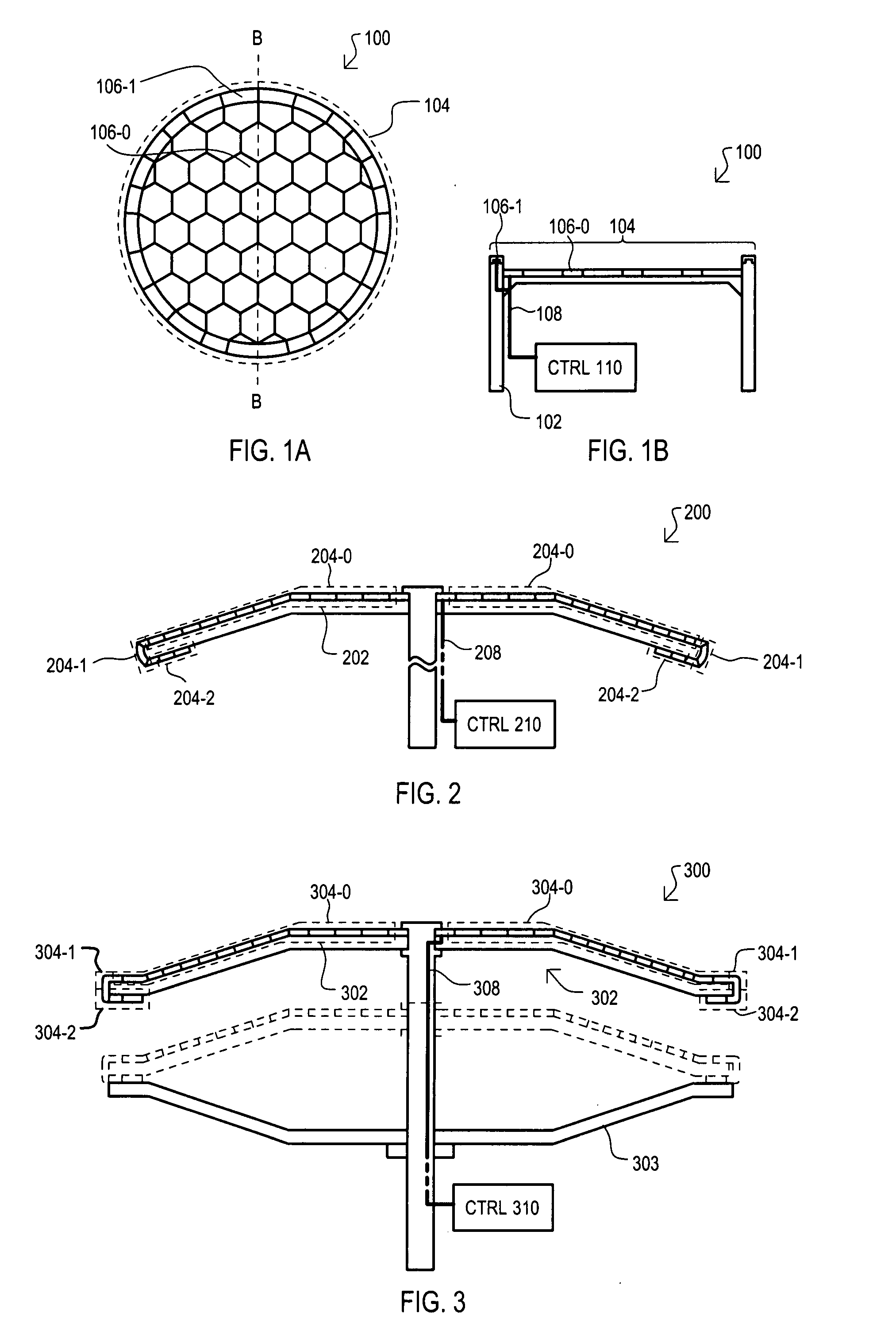
[0038]A percussion instrument is shown in a top view in FIG. 1A and a side cross sectional view in FIG. 1B, and designated by the general reference character 100. The view of FIG. 1B is taken along line B-B of FIG. 1A.
[0039]An instrument 100 can have the same general shape of a known percussion instrument, and in the very particular example of FIGS. 1A and 1B can have the shape of a “tom” type drum. An instrument 100 can include a body 102 and a playing surface 104 supported by the body 102, and a controller assembly 110.
[0040]A playing surface 104 can include one or more capacitance sensors that can provide a capacitance that can vary in response to a percussive event. In the example of FIGS. 1A and 1B, instrument 100 can include membrane sensors (one shown as 106-0) that can occupy locations of a membrane (i.e., skin or drumhead) in a conventional acoustic drum, as well as rim sensors (one shown as 106-1) that can occupy locations of a rim in a conventional acoustic drum. Capacit...
second embodiment
[0047]Referring now to FIG. 2, a percussion instrument is shown in a side cross sectional view, and designated by the general reference character 200. Percussion instrument 200 can include some of the same general sections as FIGS. 1A and 1B, thus like sections are referred to by the same reference character but with the first digit being a “2” instead of a “1”.
[0048]FIG. 2 shows an instrument having the shape of a cymbal, such as a “crash” or “ride” cymbal. As is well known, a typical cymbal has a disc-like shape with a raised bell area in a central region. The embodiment of FIG. 2 can differ from that of FIGS. 1A and 1B in that it can include multiple playing surfaces on different sides of the instrument.
[0049]In the very particular example of FIG. 2, instrument 200 can include a first playing surface 204-0 formed on a top side of the cymbal shape, a second playing surface 204-1 formed on an edge of the cymbal shape, and a third playing surface 204-2 formed on a bottom side of th...
third embodiment
[0052]Referring now to FIG. 3, a percussion instrument is shown in a side cross sectional view, and designated by the general reference character 300. Percussion instrument 300 can include some of the same general sections as FIG. 2, thus like sections are referred to by the same reference character but with the first digit being a “3” instead of a “2”.
[0053]FIG. 3 shows an instrument having the shape of a “hi-hat” type cymbal. As is well known, a typical hi-hat cymbal arrangement includes cymbals physically positioned in opposition to one another, with one or both such cymbals being capable of moving into contact with the other to generate a sound.
[0054]In the particular example of FIG. 3, instrument 300 can include a top cymbal structure 301 that can include the same components as instrument 200. Top cymbal structure 301 can be brought down into contact with a bottom symbol structure 303. In such an arrangement, playing surface 304-2 can detect such an event to generate a sound i...
PUM
 Abstract
Description
Claims
Application Information