Eureka AIR delivers breakthrough ideas for toughest innovation challenges, trusted by R&D personnel around the world.

Non-circular burst disk geometry for improved material utilization

Inactive Publication Date: 2008-10-09
AUTOLIV ASP INC
View PDF6 Cites 0 Cited by
  • Summary
  • Abstract
  • Description
  • Claims
  • Application Information

AI Technical Summary

Benefits of technology

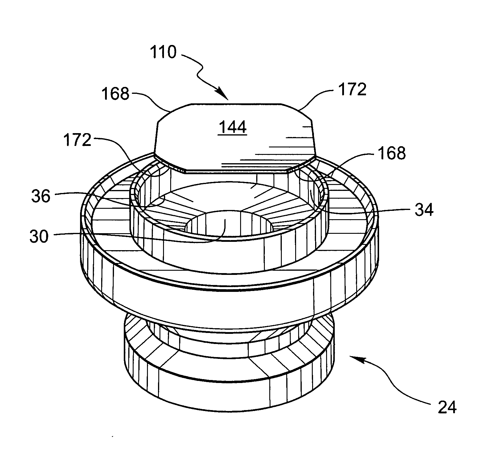
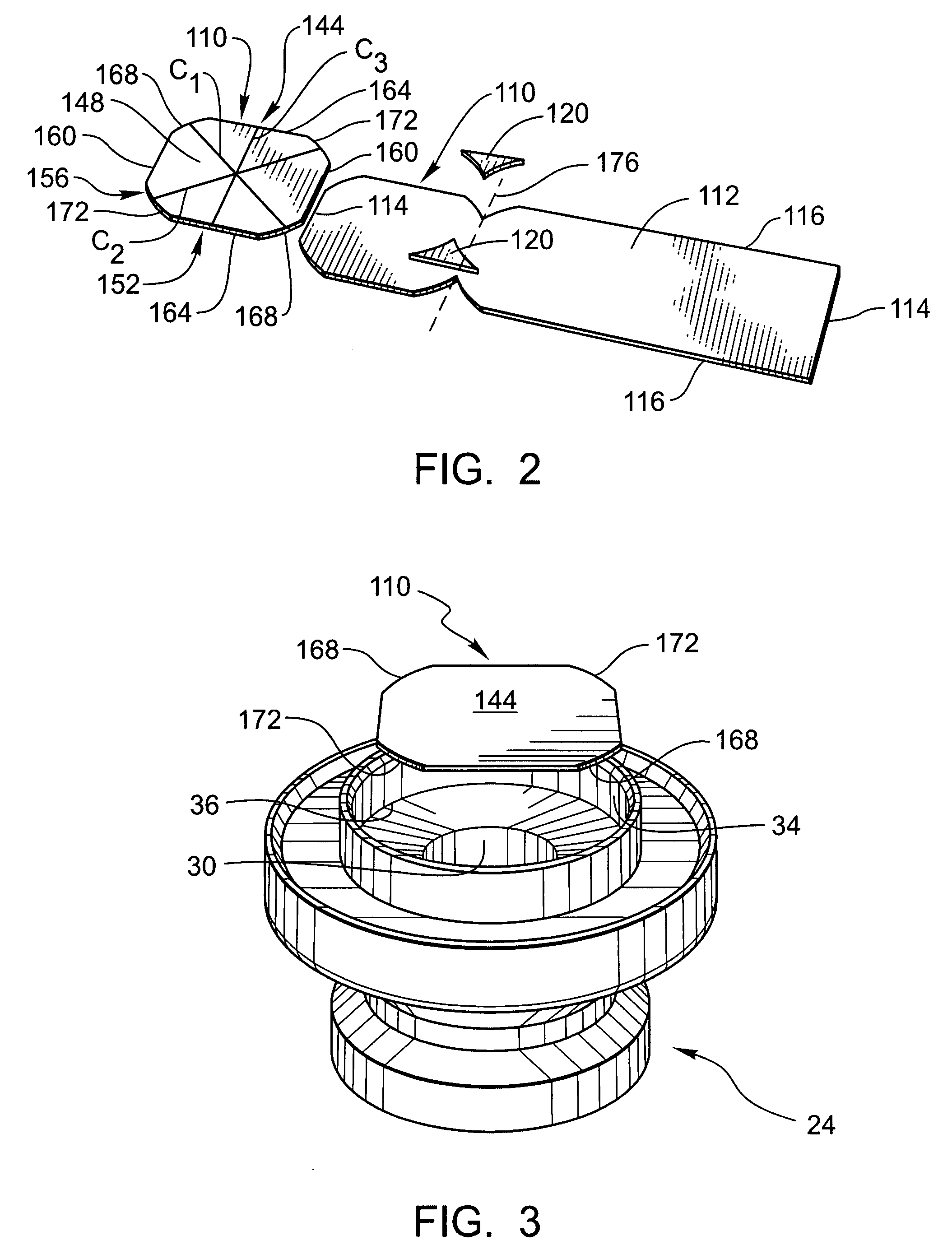
[0007]The present embodiments relate to a non-circular burst disk that may be used with an inflator that includes an orifice. In some embodiments, the inflator will also comprise a well and the orifice will be positioned at the base of the well. Accordingly, in these embodiments, the burst disk may be nested in the well to seal the orifice. The use of the well may also facilitate the proper positioning of the burst disk. However, the burst disk may also be used with inflators that do not comprise a well. In some of these embodiments that lack a well, the burst disk may be positioned via a tooling or other mechanism designed to ensure proper positioning of the burst disk.
[0010]The burst disk generally includes a surface. The surface is designed such that it may be disposed adjacent to the orifice in the inflator. The disk may be welded into the proper position. Once the disk has been welded, the disk operates to seal the orifice. By sealing the orifice, the gas stored within the inflator is prevented from exiting out of the inflator until the burst disk is ruptured (which occurs during deployment of the inflator).

Problems solved by technology

In the event of an accident or crash, the inflated airbag prevents the occupant from impacting the hard surfaces of the vehicle interior, and thus significantly reduces the likelihood that the occupant will be injured in the crash.
During deployment, this burst disk is ruptured, broken, or otherwise failed.
Once this failure of the burst disk occurs, the burst disk is not longer capable of containing the gas within the chamber.
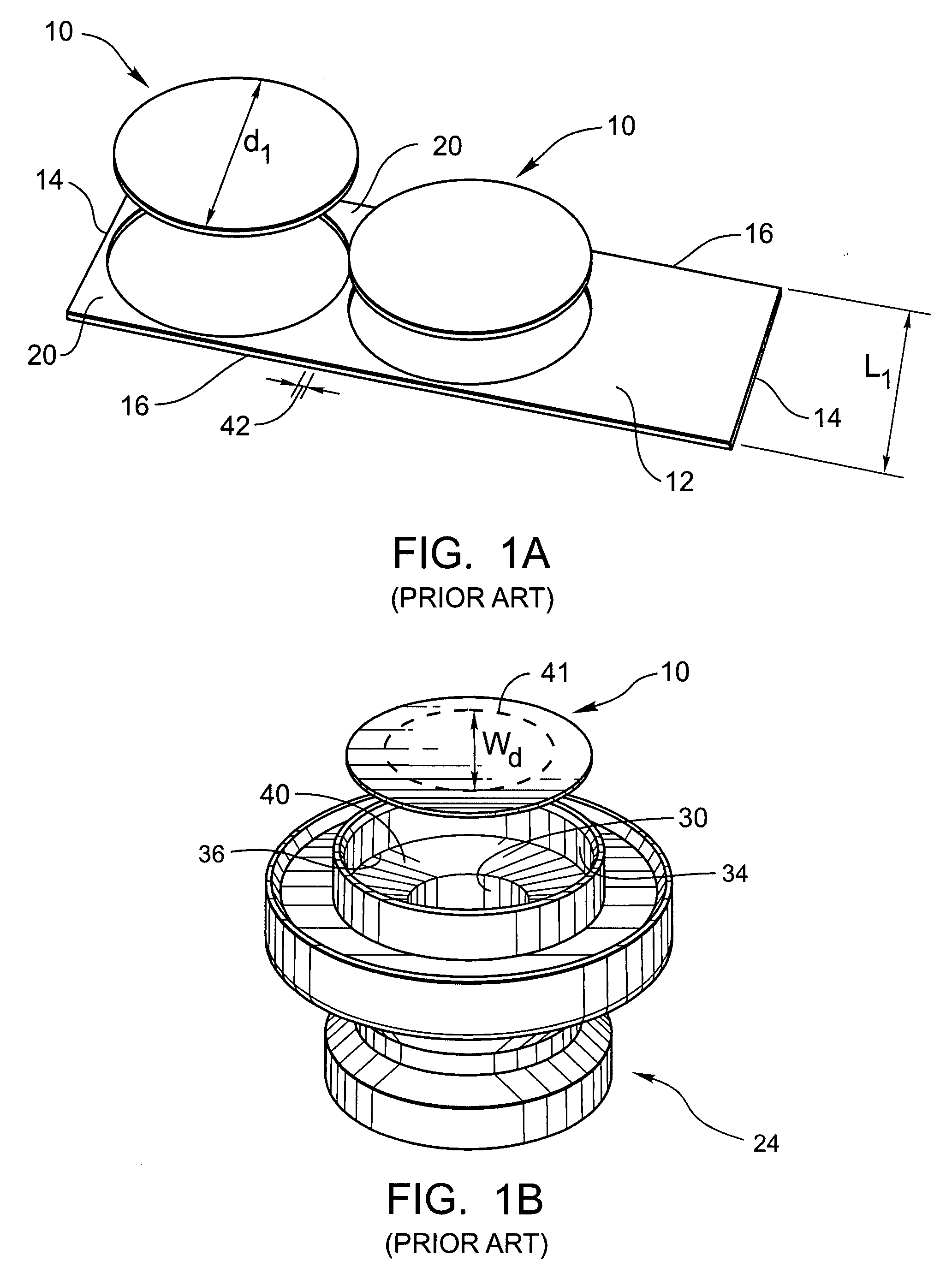
However, making the burst disk significantly larger than the orifice is wasteful and increases manufacturing costs.

Method used


Image

  • Non-circular burst disk geometry for improved material utilization
  • Non-circular burst disk geometry for improved material utilization
  • Non-circular burst disk geometry for improved material utilization

Examples


Embodiment Construction

[0022]The presently preferred embodiments of the present invention will be best understood by reference to the drawings, wherein like parts are designated by like numerals throughout. It will be readily understood that the components of the present invention, as generally described and illustrated in the figures herein, could be arranged and designed in a wide variety of different configurations. Thus, the following more detailed description of the embodiments of the present invention, as represented in the Figures, is not intended to limit the scope of the invention, as claimed, but is merely representative of presently preferred embodiments of the invention.

[0023]Referring now to FIG. 1A, a representation of the “prior art” is illustrated. Specifically, FIG. 1A is a perspective view that shows burst disks 10 that are formed (or cut) from a strip of material 12. The strip of material 12 may be much longer than it is wide in shape and has lateral width 14 and longitudinal edges 16.

[...


PUM

PropertyMeasurementUnit
Diameteraaaaaaaaaa
Shapeaaaaaaaaaa
Widthaaaaaaaaaa

Abstract

A burst disk for use in an inflator having an orifice. The burst disk includes a surface that may be disposed adjacent to the orifice. This surface includes a first side, a second side, and a non-circular perimeter, wherein at least one diagonal across the first side is greater than or equal to the diameter of the orifice. The burst disk may be generally square or rectangular in shape. By forming the burst disk in this manner, a lesser amount of raw material is needed to make the burst disk. Also, a lesser amount of material is wasted during the manufacturing process.

Description

BACKGROUND OF THE INVENTION[0001]Airbag systems are known and used in motor vehicles. These airbag systems have greatly increased the safety of motor vehicles and are designed to inflate and position an airbag in front of a vehicle occupant during a crash. A variety of different types of airbags are known including driver's airbags, passenger airbags, side curtain airbags, etc. In the event of an accident or crash, the inflated airbag prevents the occupant from impacting the hard surfaces of the vehicle interior, and thus significantly reduces the likelihood that the occupant will be injured in the crash.[0002]Airbag systems will generally include an airbag inflator (which is sometimes called an “inflator”). The inflator is designed to produce and / or channel a large quantity of inflation gas into the airbag in the event of an accident or crash. This influx of gas into the airbag inflates and deploys the airbag into the vehicle interior.[0003]Many airbag inflators include a chamber t...

Claims


Application Information

Patent Timeline
IPC IPC(8): B60R21/26
CPCB26D3/10Y10T29/49995B60R21/274B60R21/26
Inventor SMITH, BRADLEY W.CLARK, KENNETH
Owner AUTOLIV ASP INC
Why Eureka
Eureka Blog
Learn More