Eureka AIR delivers breakthrough ideas for toughest innovation challenges, trusted by R&D personnel around the world.

Data storage device mounting arrangement for printing device

a technology of data storage device and mounting arrangement, which is applied in printing, other printing devices, etc., can solve the problems of reducing the performance of the connection between the connector and damage, and achieve the effect of simplifying the connection to the data storage device and being less susceptible to damage or performance declin

Inactive Publication Date: 2010-06-08
EASTMAN KODAK CO
View PDF16 Cites 0 Cited by
  • Summary
  • Abstract
  • Description
  • Claims
  • Application Information

AI Technical Summary

Benefits of technology

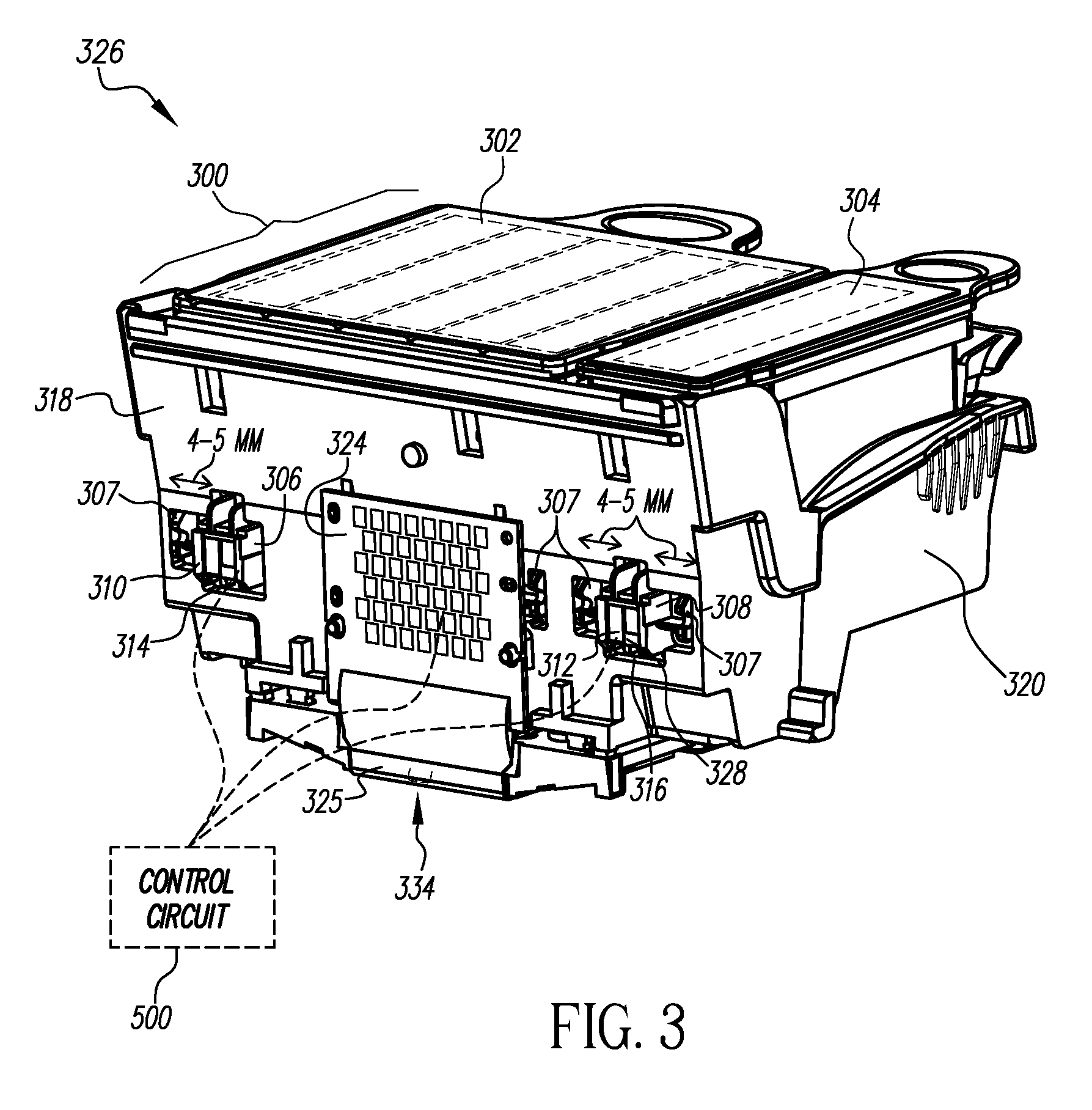
[0005]The above-described problems are addressed and a technical solution is achieved in the art by a data-storage-device mounting arrangement for fluid-ejection printing devices according to the present invention. In an embodiment of the present invention, a fluid reservoir device configured to retain fluid has a pedestal protruding therefrom. The pedestal is configured to receive a data storage device and is configured to protrude into or through an opening in a surface of a supporting structure, the supporting structure configured to support at least the fluid reservoir device. By protruding into or through an opening in a surface of the supporting structure, a disconnectable connection can be provided outside of the supporting structure and not inside of the supporting structure, thereby simplifying connectivity to the data storage device. Further, by protruding through an opening in a surface of the supporting structure, the data storage device located on the pedestal is less susceptible to damage or performance decreases due to fluid residue or leaks. Since fluid reservoirs often are recycled, saving them from damage due to ink residue can provide a cost benefit to manufacturers.
[0006]According to an embodiment of the present invention, an alignment feature, such as a datum, that facilitates proper alignment between a fluid reservoir device and its supporting structure is provided near the pedestal. Such an alignment feature, according to this embodiment, is close enough to the pedestal so that the alignment feature can further facilitate proper positioning of the pedestal into or through the opening in the surface of the supporting structure.
[0008]In an embodiment of the present invention, a signal interconnection structure is provided. The signal interconnection structure may be configured to provide signals to a printhead, export signals from the printhead, or provide signals to and export signals from the printhead. The signal interconnection structure may be connected to or integrally formed with the supporting structure. Additionally, the signal interconnection structure may be formed along a same plane or substantially a same plane as signal contacts on the data storage device when the fluid reservoir device is properly installed in the supporting structure. Such an arrangement simplifies how the data storage device and the signal interconnection structure can be connected to other circuitry.
[0009]According to an embodiment of the present invention, a fluid-providing port on a fluid reservoir device is located near the pedestal. The fluid-providing port is configured to provide fluid from the fluid reservoir device to the printhead. One advantage of providing the fluid providing port near the pedestal is that this facilitates user-friendly and reliable electrical connection, while also minimizing the fluid path length between the fluid providing port and the printhead die.

Problems solved by technology

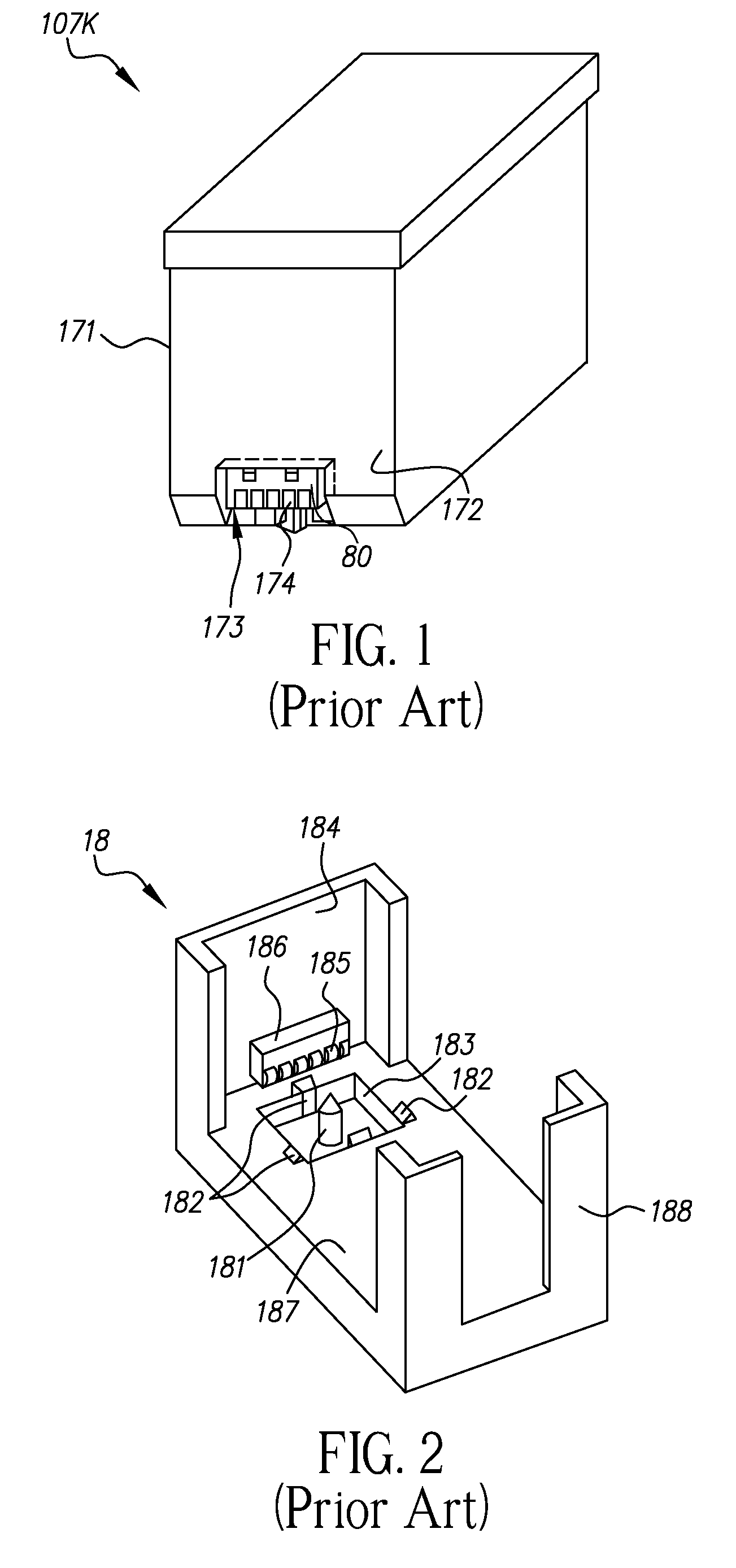
In addition, ink from the ink cartridge 107K may leak therefrom into the carriage attachment unit 18 and cause damage to or reduce the performance of the connection between the connector 186 and the data storage element 80.

Method used


Image

  • Data storage device mounting arrangement for printing device
  • Data storage device mounting arrangement for printing device
  • Data storage device mounting arrangement for printing device

Examples


Embodiment Construction

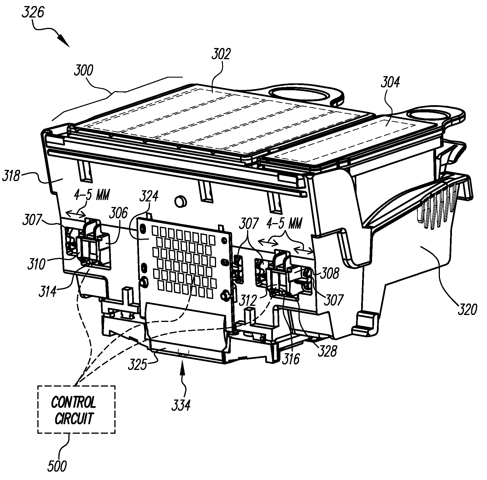
[0020]Embodiments of the present invention provide a pedestal that protrudes from a fluid reservoir device that retains fluid for a fluid-ejection printing device. A data storage device may be mounted on the pedestal such that when the fluid reservoir device is inserted into a supporting structure, the pedestal and data storage device mounted thereon protrude into or through an opening in a surface of the supporting structure. Consequently, a disconnectable connection to the data storage device may be made at a location other than the inside of the supporting structure. Accordingly, connection to the data storage device is simplified and the risk of damage or a reduction in performance to the data storage device from fluid leaks or fluid residue from the fluid reservoir device is reduced.

[0021]As an example, FIG. 3 illustrates a fluid providing system 300 in a fluid-ejection printing device 326, according to an embodiment of the present invention. Although not required, the fluid-ej...


PUM


Abstract

The present invention provides a pedestal that protrudes from a fluid reservoir device that retains fluid for a fluid-ejection printing device. A data storage device may be mounted on the pedestal such that when the fluid reservoir device is inserted into a supporting structure, the pedestal and data storage device mounted thereon protrude into or through an opening in a surface of the supporting structure. Consequently, a disconnectable connection to the data storage device may be made at a location other than the inside of the supporting structure. Accordingly, connection to the data storage device is simplified and the risk of damage or a reduction in performance to the data storage device or its electrical contacts from fluid leaks from the fluid reservoir device is reduced.

Description

FIELD OF THE INVENTION[0001]This invention relates to a data-storage-device mounting arrangement for a fluid-ejection printing device. In particular, this invention pertains to a data-storage-device mounting arrangement that facilitates simplified connectivity and reduced risk of damage to the data storage device from fluid leaks.BACKGROUND OF THE INVENTION[0002]Recently, fluid-ejection printing devices, such as ink jet printers have incorporated data storage devices into their fluid reservoir devices in order to track the amount of fluid remaining in the reservoir as well as other important information. Typically, the amount of ink that has been used by fluid ejection and / or by maintenance operations is tracked by counting drop ejection events or maintenance events and multiplying by the amount used per event. Data related to the amount of fluid that has been consumed (starting from a known amount), or the amount of fluid that remains, is stored in the data storage device. In any c...

Claims


Application Information

Patent Timeline
Patent Type & Authority Patents(United States)
IPC IPC(8): B41J2/14B41J2/175
CPCB41J2/1752B41J2/17546B41J2/1753
Inventor TRAFTON, R. WINFIELDPETRANEK, DIANA C.PERKINS, MARK D.
Owner EASTMAN KODAK CO
Why Eureka
Eureka Blog
Learn More