CAN remote communication system based on optical transceiver

A technology of long-distance communication and optical transceiver, which is applied in the field of CAN long-distance communication system to achieve the effect of improving signal anti-interference ability and avoiding electromagnetic radiation

Pending Publication Date: 2022-02-11
成都奥瑞科电子科技有限公司
View PDF0 Cites 0 Cited by
  • Summary
  • Abstract
  • Description
  • Claims
  • Application Information

AI Technical Summary

Problems solved by technology

[0003] The purpose of the present invention is to overcome the deficiencies in the prior art, adopt the CAN optical transceiver scheme, can solve the problem that the farthest transmission distance of the CAN bus is less than 40m at a rate of 1Mbps, and extend the communication distance of the CAN bus to a transmission distance of tens of kilometers through optical transmission CAN long-distance communication system based on optical transceiver

Method used


Image

  • CAN remote communication system based on optical transceiver
  • CAN remote communication system based on optical transceiver
  • CAN remote communication system based on optical transceiver

Examples


Embodiment Construction

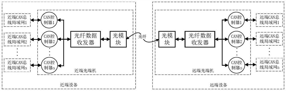
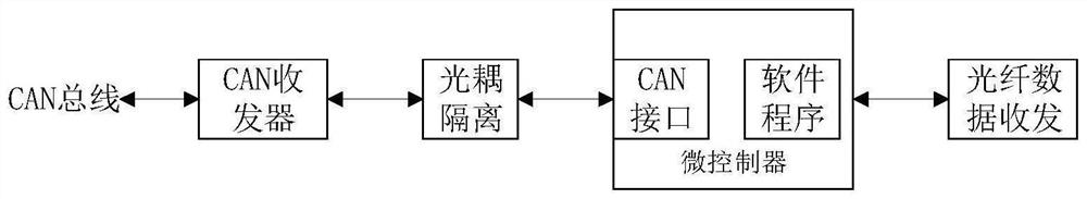
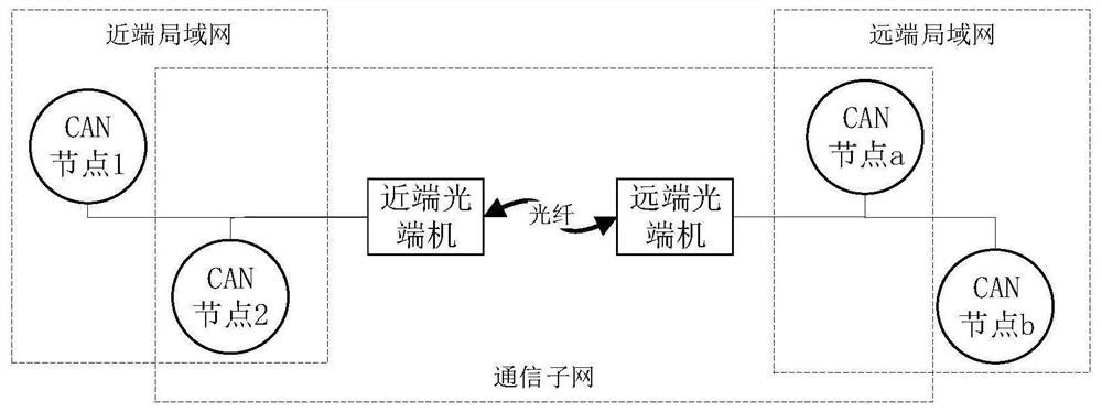
[0023] The present invention is a design that extends the CAN bus from a maximum 40m communication distance into a transmission distance of dozens of kilometers, and the optical-based CAN remote communication system includes a proximal optical terminal and a remote optical terminal, distal and proximal optical terminal. The design is the same, including hardware design and software design.

[0024] By implementing the CAN bus controller, the agent function of the remote CAN bus terminal is implemented, thereby achieving the functional indicators of increasing the CAN bus transmission distance; by using the optical module, the electrical signal is converted to the optical signal, and the CAN bus data is transmitted in the fiber. Improve the anti-interference capability of the CAN bus expansion network; by integrated multi-channel data packaging, data unpacking distribution functions, allowing the design to support the extension of multiple sets of CAN bus networks.

[0025] The tec...


PUM


Abstract

The invention discloses a CAN remote communication system based on an optical transceiver. The system comprises a near-end device and a far-end device which are connected through an optical fiber. The near-end device and the far-end device each comprise an optical module, an optical fiber data transceiver, a CAN controller and a CAN bus local area network which are connected in sequence. According to the invention, the maximum communication distance of the CAN bus is expanded to the transmission distance of dozens of kilometers from the maximum communication distance of 40m through optical transmission; signals are transmitted through optical fibers, so that the signal anti-interference capability of the system is improved; the far-end device and the near-end device can complete network expansion of multiple groups of CAN buses only through one optical fiber, so the problem that the two devices are connected through multiple cables is simplified, and the problems of electromagnetic radiation, electromagnetic shielding and the like caused by cable connection are avoided; and the two optical transceivers are respectively deployed in a far-end device and a near-end device. The limited range of the CAN bus expansion network subnet can be self-defined according to the specific requirements of a user.

Description

Technical field [0001] The present invention belongs to the field of communication, and in particular, the present invention relates to an optical-based CAN long-range communication system. Background technique [0002] Optical-end supporting the CAN bus remote communication is mainly used in vehicle electronic devices. Due to the real-time performance of the CAN bus, the transmission distance cannot exceed 40m when the CAN bus rate is 1 Mbps. At this stage, the actual transmission distance of the CAN bus has exceeded 40m. In some specific occasions, it is necessary to optimize the multi-cable signal to a fiber to signal transmission. Due to the response time loss due to photoelectric conversion, the transmission distance is more than 40m. Shorter. At this time, the transport distance of the CAN bus will restrict the functional design of the system. Inventive content [0003] It is an object of the present invention to overcome the deficiencies of the prior art, and the CAN opti...

Claims


Application Information

Patent Timeline
Patent Type & Authority Applications(China)
IPC IPC(8): H04L12/40H04B10/40
CPCH04L12/40006H04B10/40H04L2012/40215
Inventor 吕静聂锐
Owner 成都奥瑞科电子科技有限公司
Why Eureka
Try Eureka