Fluid-ejecting device with simplified connectivity

a technology of fluide-ejecting devices and connectivity, applied in printing, other printing apparatuses, etc., can solve problems such as frequent failure sources, and achieve the effect of simplifying connectivity

Inactive Publication Date: 2010-10-12
EASTMAN KODAK CO
View PDF12 Cites 1 Cited by
  • Summary
  • Abstract
  • Description
  • Claims
  • Application Information

AI Technical Summary

Benefits of technology

[0006]The above-described problems are addressed and a technical solution is achieved in the art by a fluid-ejecting device with simplified connectivity according to the present invention. According to an embodiment of the present invention, a fluid-ejecting device is provided that includes one or more fluid-ejecting chips, each including a plurality of first electrical contacts. Also included is a single-layer-flex circuit having a plurality of second electrical contacts connected to the plurality of first electrical contacts. One of the second electrical contacts is a common lead, thereby allowing a plurality of third electrical contacts located remote from the fluid-ejecting chip(s) on the single-layer-flex circuit to be fewer in number than the first electrical contacts. In other words, by providing a common lead as one of the contacts on the single-layer-flex circuit adjacent the fluid-ejecting chip(s), the number of contacts needed at an edge (or a remote location) on the single-layer-flex circuit is reduced over conventional fluid-ejecting devices.
[0007]According to another embodiment of the present invention, more than one common lead is provided as part of the second electrical contacts. Additionally, according to a further embodiment of the present invention, bond sites extend towards the fluid-ejecting chip(s) from the common leads in order to reduce the distance required to connect a wire bond from the common leads to the first electrical contacts.

Problems solved by technology

Because the wire bonds 30 are fragile, they are frequently the source of failure.

Method used


Image

  • Fluid-ejecting device with simplified connectivity
  • Fluid-ejecting device with simplified connectivity
  • Fluid-ejecting device with simplified connectivity

Examples


Embodiment Construction

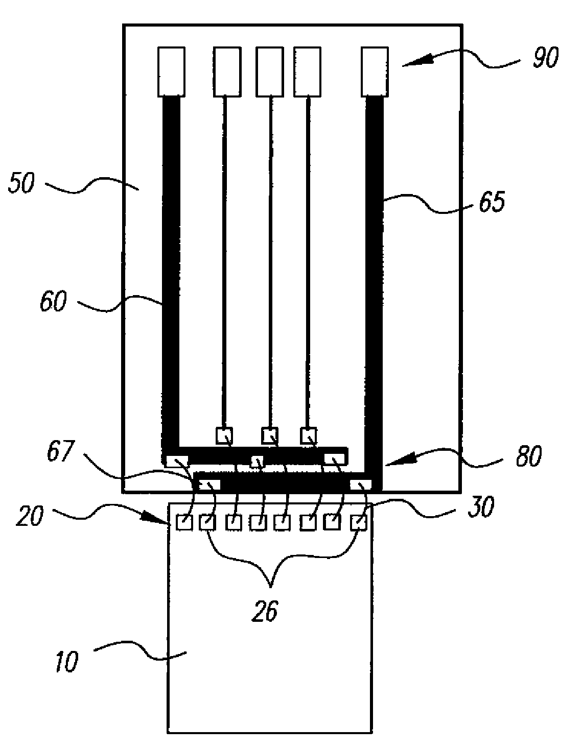
[0018]The present invention reduces the complexity of connecting a fluid-ejecting chip to a single-layer-flex circuit by providing at least one common lead to which more than one electrical contact on a fluid-ejecting chip connects. Accordingly, because the common lead(s) on the single-layer-flex circuit adjacent the fluid-ejecting chip act(s) as a single electrical contact for a plurality of contacts on the fluid-ejecting chip, fewer signals need to be routed to the contacts on the edge of the single-layer-flex circuit adjacent the fluid-ejecting chip. Such fewer signals reduces the size and the complexity of the circuit, thereby reducing the cost of producing the overall fluid-ejecting device 101.

[0019]Additionally, the present invention provides an arrangement of electrical contacts on the single-layer-flex circuit adjacent the fluid-ejecting chip that minimizes the length of the associated wire bonds. Such an arrangement further reduces the complexity of a fluid-ejecting device ...


PUM


Abstract

A fluid-ejecting device with simplified connectivity is disclosed herein. According to an embodiment of the present invention, a common lead is provided such that a plurality of electrical contacts on a fluid-ejecting chip are connected to the common lead, which is located on a single-layer-flex circuit. Because a common lead is provided at an edge of the single-layer-flex circuit adjacent the fluid-ejecting chip, fewer signals need to be routed through the single-layer-flex circuit to such edge, thereby reducing the complexity of such circuit. Further, bond sites at the edge of the single-layer-flex circuit adjacent the fluid-ejecting device are arranged in a manner that minimizes the required length of wire bonds for connecting such contacts to the contacts on the fluid-ejecting chip.

Description

FIELD OF THE INVENTION[0001]This invention relates to fluid-ejecting devices. In particular, the present invention pertains to fluid-ejecting devices, such as ink jet printing devices, with simplified connectivity.BACKGROUND OF THE INVENTION[0002]FIG. 1 illustrates a conventional ink jet print head 101. The print head 101 includes an ink reservoir (not shown) which provides ink to a plurality of nozzles 107 arranged in a plurality of rows on fluid-ejecting chips 110. In order to print an image with the print head 101, electrical signals are transmitted to the print head 101 that selectively provide electrical current to particular nozzles 107 causing such nozzles to heat up and eject ink at appropriate points in time to create an image on a substrate. Such electrical signals are provided to the nozzles 107 from a driving circuit (not shown) to contacts 195 located on a printed-circuit (“PC”) board 151. The contacts 195 are conductively connected to contacts 190 located on a single-l...

Claims


Application Information

Patent Timeline
Patent Type & Authority Patents(United States)
IPC IPC(8): B41J2/05
CPCB41J2/14072B41J2/1753
Inventor CIMINELLI, MARIO J.ORLICKI, DAVID M.MORTON, CHRISTOPHER R.
Owner EASTMAN KODAK CO
Why Eureka
Try Eureka