Phase winding

A technology of phase winding and combined coil, which is applied in the field of phase winding, can solve the problems of inconsistent height, appearance, and form of the bending part, poor consistency of the torsion direction of the welding end, and the failure of the bending part to be consistent, etc., to shorten the spanning distance , Avoid mutual entanglement, simple connection and simplified effect

Pending Publication Date: 2020-05-15
CHONGQING ZONGSHEN ELECTRIC POWER TECH CO LTD
View PDF2 Cites 0 Cited by
  • Summary
  • Abstract
  • Description
  • Claims
  • Application Information

AI Technical Summary

Problems solved by technology

It has the following characteristics: 1. The flat wire conductor is bent and formed at one time, including the head, leg, straight line, and pre-formed point. The two legs of the conductor and one pre-formed point are the welding side, and the head is the non-welding side; Many folding steps, complicated control and low efficiency
2. The torsion direction of the welding end has poor consistency, the height, appearance and form of the bending part are inconsistent, and the bending part cannot be consistent
3. The process is complicated. The preformed flat wire conductors are rolled off one by one from the inner diameter of the stator core to the outside. Since the preformed flat wire conductors are only suitable for the stator core with an open slot, slot wedge support is required.

Method used


Image

  • Phase winding
  • Phase winding
  • Phase winding

Examples


Embodiment 1

[0067] Embodiment 1: as Figure 5-14 As shown, the purpose of this embodiment is to provide a phase winding, a stator 100 and a motor, the motor includes a motor and a generator, and also includes a unidirectional motor and a multi-phase motor.

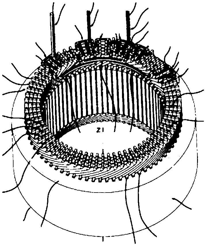
[0068] Wherein, the stator includes a stator core 1, and the stator core includes a substantially cylindrical main body 11, and a plurality of stator core slots opening inwards are provided along the circumference of the inner ring of the stator core. 12, that is to say, the opening of the stator core slot faces the central axis (z1-z2) of the stator core, one end of the stator core slot is the insertion side 13, and the other end is the connection side 14, in the A unidirectional or multi-phase winding 10 is arranged in the slot of the stator core, and each phase winding 2 is formed by overlapping and radially displacing more than one coil ring 3 along the circumferential direction of the stator core, and each coil ring 3 is formed b...

Embodiment 2

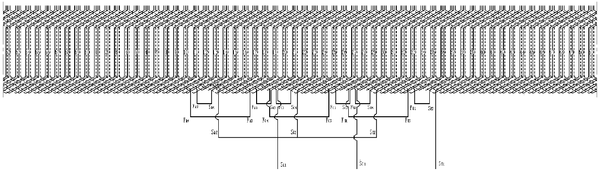
[0088] Embodiment 2: as Figure 5 , 6 , 15-24, the purpose of this embodiment is to provide a phase winding, a stator and a motor, the motor includes a motor and a generator, and also includes a unidirectional motor and a multi-phase motor.

[0089] Wherein, the stator includes a stator core 1, and the stator core includes a substantially cylindrical main body 11, and a plurality of stator core slots opening inwards are provided along the circumference of the inner ring of the stator core. 12, that is to say, the opening of the stator core slot faces the central axis (z1-z2) of the stator core, one end of the stator core slot is the insertion side 13, and the other end is the connection side 14, in the A three-phase winding 10 is arranged in the slot of the stator core, and each phase winding 2 is formed by overlapping and radially displacing more than one coil ring 3 along the circumferential direction of the stator core, and each coil ring is formed by a plurality of combin...

Embodiment 3

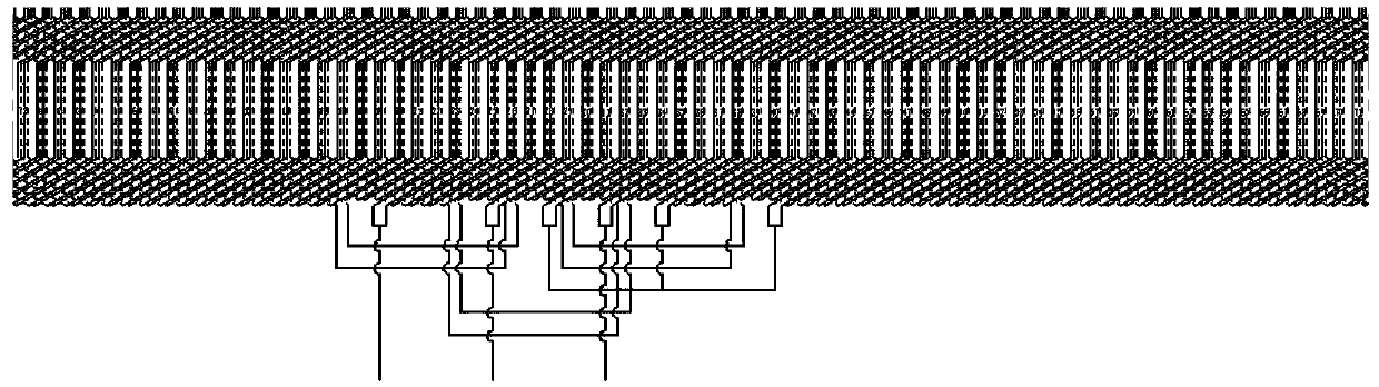
[0111] Embodiment 3: as Figure 25-27 As shown, this embodiment is an improvement made on the basis of Embodiment 1 and Embodiment 2. In this embodiment, the phase winding can be composed of more than one C2 type coil ring and / or more than one Cn type coil ring along the stator The iron cores are overlapped or arranged in dislocation in the circumferential direction; wherein, the C2-type coil ring is formed by connecting a plurality of combined coils C2 end to end along the circumferential direction of the stator core; the Cn-type coil ring is formed by a plurality of combined coils Cn along the stator iron core. The core is formed by end-to-end connection in the circumferential direction.

[0112] For example, when A=8, two turns of C2-type coil rings can be arranged in overlapping or dislocation in the circumferential direction of the stator core; Coil ring and 1 turn of C3 type coil ring constitute, and so on.

[0113] In this embodiment, it is shown that when A=8, a stat...


PUM


Abstract

The invention discloses a phase winding which is formed by stacking more than one coil ring. Each coil ring is formed by connecting a plurality of combined coils end to end, and each combined coil isat least formed by winding a first kind of partial U-shaped conductor and a second kind of partial U-shaped conductor, wherein each of the first-class partial U-shaped conductor and the second-class partial U-shaped conductor comprises a head part, two supporting leg parts and two supporting legs which are connected with one another, and the two supporting legs of the same conductor are deflectedtowards the same side; the supporting legs of the first kind of partial U-shaped conductors and the supporting legs of the second kind of partial U-shaped conductors are opposite in deflection direction, and the connecting head parts and the two supporting leg parts of the first kind of partial U-shaped conductor and the second kind of partial U-shaped conductor are overlapped with each other. Bythe adoption of the phase winding, a bridging distance is short, the use amount of the invalid copper is reduced, and the serialized production and design are facilitated.

Description

Technical field: [0001] The invention relates to a phase winding, in particular to a stator phase winding of a motor. Background technique: [0002] Motors (including motors and generators) are devices that convert electrical energy into mechanical energy (or convert mechanical energy into electrical energy) based on the principle of electromagnetic induction. Power source or generating device. Motors can be divided into DC motors and AC motors according to the type of their working power, and AC motors can be divided into single-phase motors and multi-phase motors (such as three-phase motors, etc.). The motor includes a stator and a rotor, and a winding is arranged in a stator core slot of the stator. [0003] There are two types of existing motor windings: wave winding and stacked winding. For segmental hairpin winding motors using flat copper wires or copper wires with rectangular cross-sections, the use of stacked windings will cause too many jumper conductors between ...

Claims


Application Information

Patent Timeline
Patent Type & Authority Applications(China)
IPC IPC(8): H02K3/04H02K3/28
CPCH02K3/04H02K3/12H02K3/28H02K2213/03
Inventor 邵俊山黄朝东
Owner CHONGQING ZONGSHEN ELECTRIC POWER TECH CO LTD
Why Eureka
Try Eureka