Supercharge Your Innovation With Domain-Expert AI Agents!

Negative voltage converter

a negative voltage converter and converter technology, applied in the direction of power conversion systems, dc-dc conversion, instruments, etc., can solve the problems of increasing the complexity of design, different threshold voltages of p-type tft, and reducing the yield of products accordingly

Active Publication Date: 2008-10-16
AU OPTRONICS CORP
View PDF25 Cites 1 Cited by
  • Summary
  • Abstract
  • Description
  • Claims
  • Application Information

AI Technical Summary

Benefits of technology

"The present invention provides a negative voltage converter that uses a P-type TFT independent of threshold voltage. The converter includes a signal input end, a signal output end, and a plurality of transistors. The transistors are arranged in a circuit to amplify and control the voltage of the signal. The invention also includes a plurality of voltage amplifying circuits that further amplify the signal. The technical effect of the invention is to provide a more efficient and accurate negative voltage converter that is independent of the input clock signal and can control the voltage of the signal more effectively."

Problems solved by technology

However, a difference in P-type TFT fabrication process may result in different threshold voltage of P-type TFT.
Such deviation directly influences on an operation subsequent stage of circuits and components, increasing complexity of design, and reducing yield of products accordingly.

Method used


Image

  • Negative voltage converter
  • Negative voltage converter
  • Negative voltage converter

Examples


Embodiment Construction

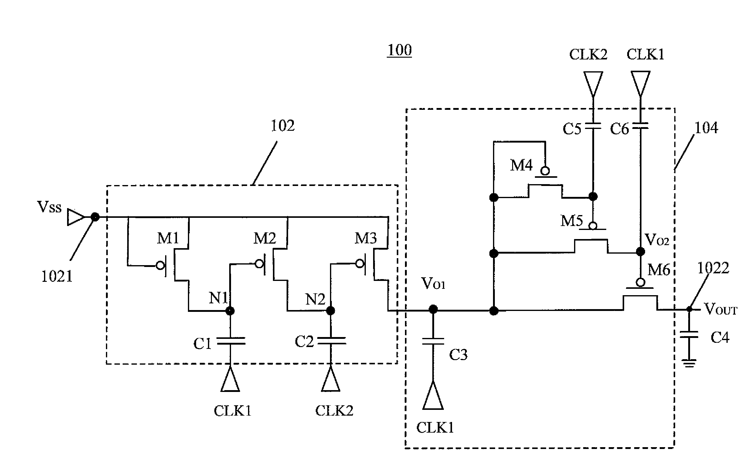
[0021]FIG. 4 shows a circuit diagram of a negative voltage converter 100 according to a first preferred embodiment of the present invention. The negative voltage converter 100 comprises an input circuit 102 for delivering a DC voltage Vss applied on a signal input end 1021 to the voltage amplifying circuit 104, and a voltage amplifying circuit 104 for amplifying the DC voltage Vss to a required negative voltage at a signal output end 1022.

[0022]The voltage amplifying circuit 102 comprises a first transistor M1, a second transistor M2, a third transistor M3, each of which may be implemented by a P-type TFT. A control end of the first transistor M1 connects with the signal input end 1021 of the negative voltage converter 100. A first end of the first transistor M1 is electrically coupled to the signal input end 1021. A first end of the second transistor M2 is also electrically coupled to the signal input end 1021. A control end of the second transistor M2 is electrically coupled to a ...


PUM


Abstract

A negative voltage converter includes six transistors. A first end and a control end of a first transistor are coupled to a signal input. A first end of a second transistor is coupled to the signal input, and a control end of which is coupled to a first clock and the first transistor. A first end of a third transistor is coupled to the signal input, a control end of the third transistor is coupled with a second clock and the second transistor. A first end of a fourth transistor is coupled to the second end of the third transistor, a control end of which is coupled with the first clock and the third transistor. A first end of a fifth transistor is coupled to the second end of the third transistor, and a control end of which is coupled with the second clock and the fourth transistor A first end of a sixth transistor is coupled to the second end of the third transistor, and a control end of which is coupled with the first clock and the fifth transistor.

Description

BACKGROUND OF THE INVENTION[0001]1. Field of the Invention[0002]The present invention relates to a negative voltage converter, and more particularly to a negative voltage converter using P-type thin film transistors (P-type TFTs).[0003]2. Description of the Related Art[0004]Referring to FIG. 1 and FIG. 2, FIG. 1 is a circuit diagram of a negative voltage converter 10 using P-type TFTs according to prior art. FIG. 2 shows a relationship of voltage applied on a node X depicted in FIG. 1 varied with a threshold voltage Vth of the transistor 16. The Negative voltage converter 10, using P-type Thin Film Transistors (P-type TFTs), is capable of transforming an input positive voltage or zero voltage into a negative direct current (DC) voltage to be desired by a circuit or a component. The negative converter 10 comprises an input circuit 12 and a voltage amplifying circuit 14. The input circuit 12 comprises a P-type TFT 16 and a capacitor 18 electrically coupled to a clock signal CLK. The v...

Claims


Application Information

Patent Timeline
Patent Type & Authority Applications(United States)
IPC IPC(8): G05F1/10
CPCH02M3/073H02M2003/071H02M3/071
Inventor LEE, KUNG-HONGPAI, CHENG-CHIULU, SHI-HSIANGSUN, WEIN-TOWN
Owner AU OPTRONICS CORP
Features
  • R&D
  • Intellectual Property
  • Life Sciences
  • Materials
  • Tech Scout
  • Unparalleled Data Quality
  • Higher Quality Content
  • 60% Fewer Hallucinations
Learn More