
Printhead assembly incorporating heat aligning printhead modules

a printhead and module technology, applied in the field of printers, can solve the problems of relative high production and operating costs

Inactive Publication Date: 2008-10-23
SILVERBROOK RES PTY LTD +1
View PDF7 Cites 0 Cited by
  • Summary
  • Abstract
  • Description
  • Claims
  • Application Information

AI Technical Summary

Benefits of technology

[0013]By allowing the structural component of the support to thermally expand relative to the mounting component, the structural components can be strong, inexpensive metal despite the co-efficient of thermal expansion (CTE). Only the mounting component need approximate the CTE of the printhead chips to maintain a suitable alignment of the modules.

Problems solved by technology

The high defect rate translates into relatively high production and operating costs.

Method used


Image

  • Printhead assembly incorporating heat aligning printhead modules
  • Printhead assembly incorporating heat aligning printhead modules

Examples


Embodiment Construction

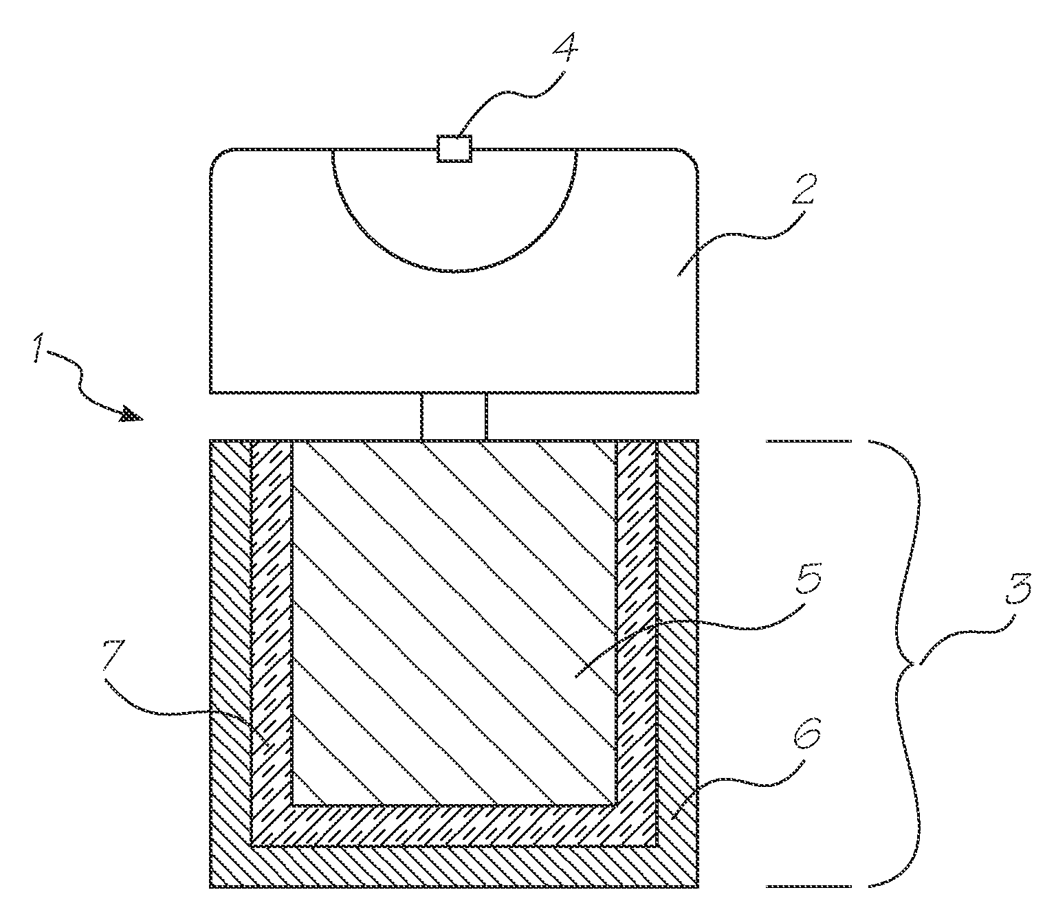
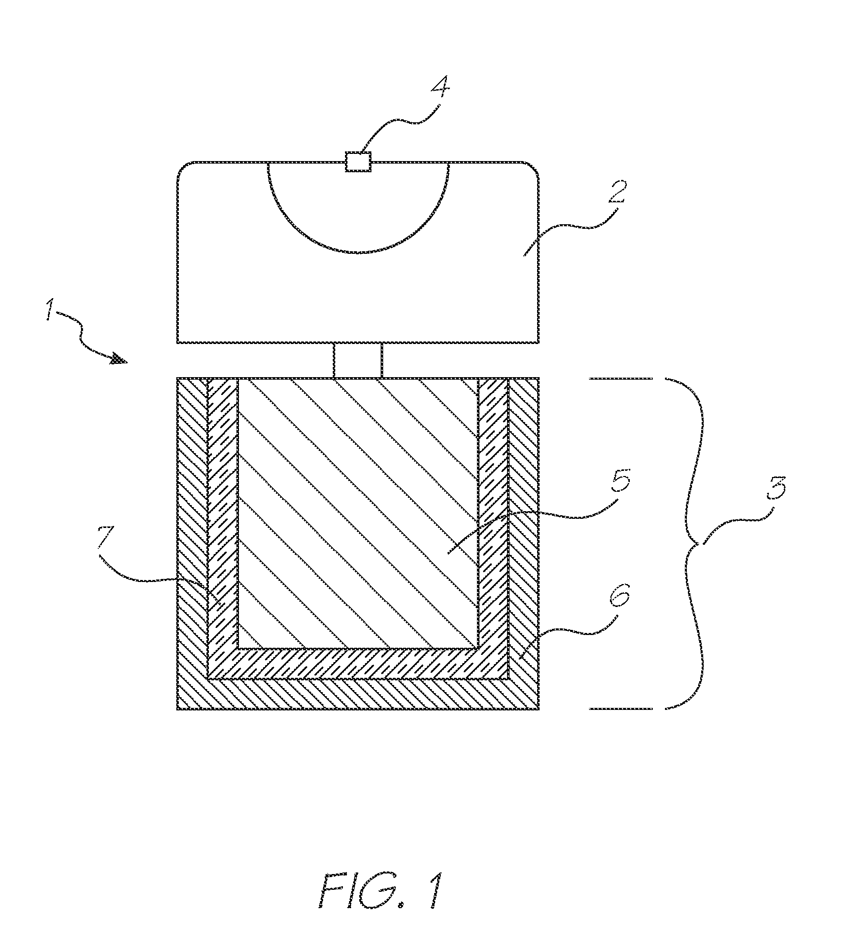
[0030]Referring to the figure the printhead assembly 1 has a plurality of printhead modules 2 mounted to a support member 3 in a printer (not shown). The printhead module includes a silicon printhead chip 4 in which the nozzles, chambers, and actuators are manufactured using MEMS techniques. Each printhead chip 4 has at least 1 fiducial (not shown) for aligning the printheads. Fiducials are reference markings placed on silicon chips and the like so that they may be accurately positioned using a microscope.

[0031]According to one embodiment of the invention, the printheads are aligned while the printer is operational and the assembly is at the printing temperature. If it is not possible to view the fiducial marks while the printer is operating, an alternative system of alignment is to misalign the printhead modules on the support beam 3 such that when the printhead assembly heats up to the operating temperature, the printheads move into alignment. This is easily achieved by adjusting ...


PUM

PropertyMeasurementUnit
Temperatureaaaaaaaaaa

Abstract

The present invention relates to a printhead assembly for a printer. The assembly includes a support member. A plurality of printhead modules is mounted to the support member. Each printhead module includes an integrated circuit manufactured using micro-electromechanical systems (MEMS) techniques. The printhead modules are configured to move into alignment with each other upon heating of the printhead assembly.

Description

CROSS REFERENCE TO RELATED APPLICATION[0001]The present application is a continuation of U.S. application Ser. No. 11 / 330,057 filed on Jan. 12, 2006 which is a continuation of U.S. application Ser. No. 10 / 882,764 filed on Jul. 2, 2004, which is a continuation of U.S. application Ser. No. 10 / 129,437 filed on Jun. 6, 2002, now issued as U.S. Pat. No. 6,793,323, which is a 371 of PCT / AU01 / 00260 filed on Mar. 9, 2001, all of which are herein incorporated by reference.FIELD OF THE INVENTION[0002]The present invention relates to printers, and in particular to inkjet printers.CO-PENDING APPLICATIONS[0003]Various methods, systems and apparatus relating to the present invention are disclosed in the following co-pending applications filed by the applicant or assignee of the present invention on 24 May 2000:PCT / AU00 / 00578PCT / AU00 / 00579PCT / AU00 / 00581PCT / AU00 / 00580PCT / AU00 / 00582PCT / AU00 / 00587PCT / AU00 / 00588PCT / AU00 / 00589PCT / AU00 / 00583PCT / AU00 / 00593PCT / AU00 / 00590PCT / AU00 / 00591PCT / AU00 / 00592PCT / AU0...

Claims


Application Information

Patent Timeline
IPC IPC(8): B41J2/14B41J2/16
CPCB41J2/14024Y10T29/49401B41J2202/03B41J2/235
Inventor SILVERBROOK, KIA
Owner SILVERBROOK RES PTY LTD
Learn More