Saw blade

a technology of blades and blades, applied in the field of blades, can solve the problems of shortening the maximum life of blades, less durable, and cracking of the tip/plate interfa

Inactive Publication Date: 2008-10-30
BLACK & DECKER INC
View PDF29 Cites 38 Cited by
  • Summary
  • Abstract
  • Description
  • Claims
  • Application Information

AI Technical Summary

Problems solved by technology

The conventional saw blade having a tip brazed onto each tooth, while relatively straight forward to manufacture, is less durable and has a shorter maximum life, especially in abusive situations such

Method used


Image

  • Saw blade
  • Saw blade
  • Saw blade

Examples


Embodiment Construction

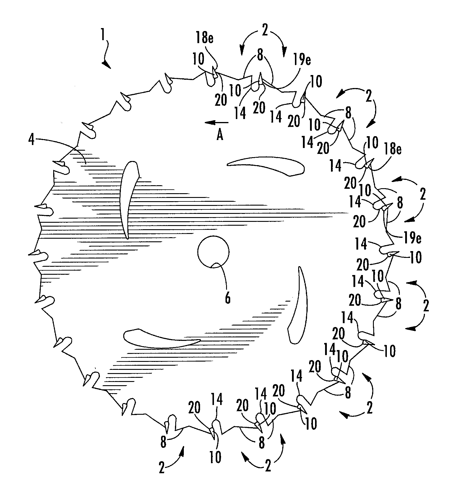
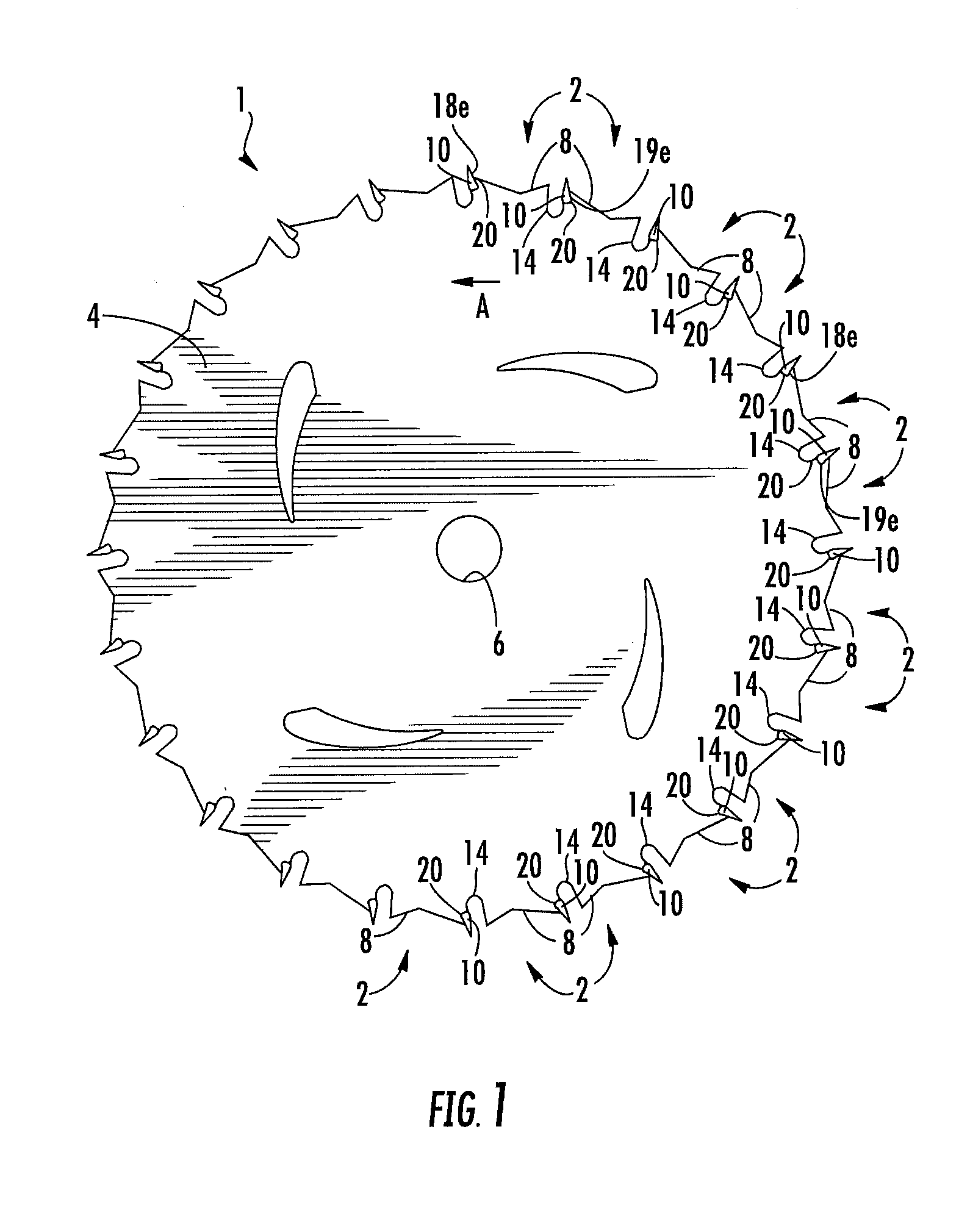
[0013]FIG. 1 shows a side view of one embodiment of the saw blade 1 of the invention. Blade 1 is a circular saw blade and has twenty-four teeth 2 arranged about the periphery of plate 4. It is to be understood that the invention can be used with a saw blade having any number of teeth and that the twenty-four tooth blade is used by way of example only. A hole 6 is centrally located in plate 4 to attach the saw blade to the arbor of a rotary tool such as a circular saw, table saw, powered miter saw or the like in a known manner. The blade 1 is rotated in the direction of arrow A by the rotary tool as is known in the art.

[0014]Each tooth 2 consists of a tooth support 8 supporting cutting tip 10. Tooth support 8 may be formed integrally with the plate 4, and extends radially from the periphery of the plate 4. A gullet 14 may be formed between each of the teeth defining the areas between the teeth. In one embodiment cutting tip 10 is formed of a hard material such as tungsten carbide wel...


PUM

PropertyMeasurementUnit
Lengthaaaaaaaaaa
Shapeaaaaaaaaaa

Abstract

A saw blade comprises a plate having a plurality of teeth. Each of the teeth includes a tip where the tip has a smooth curved surface welded to the plate. The tip comprises a solid piece of hard material and has a generally rounded wedge shape. A method of forming a saw blade having cutting tips welded to the plate is also provided.

Description

BACKGROUND OF THE INVENTION[0001]Saw blades comprising a steel plate having a plurality of teeth formed on the plate are known. The teeth may comprise a tooth formed integrally with the plate with a tip is brazed onto each tooth. The conventional saw blade having a tip brazed onto each tooth, while relatively straight forward to manufacture, is less durable and has a shorter maximum life, especially in abusive situations such as nail strikes, than is desirable. Attempts to weld traditionally shaped tips onto the steel plate have resulted in cracking in the tip / plate interface due to stresses caused by the welding process. Further, in order to be cost effective, any process for attaching the tips to the plate must not require extensive subsequent processes to obtain the final tip geometry.[0002]Thus, an improved saw blade tooth construction, saw blade and blade manufacturing process that allow the tip to be welded to the plate in a manner that provides a strong tip / plate interface an...

Claims


Application Information

Patent Timeline
IPC IPC(8): B23D57/00
CPCB23D61/04B23D65/00Y10T83/9319
Inventor COE, ANDREWDAVIDSON, CRAIGGILLANDERS, MATTHEWHALL, KENMURPHY, MARTINWALTON, BARRY
Owner BLACK & DECKER INC
Why Eureka
Try Eureka