Protective cup and method of manufacturing the protective cup

a protective cup and cup body technology, applied in the field of protective cups, can solve the problems of tiring of wearing for an extended period, and restricting the movement of the wearer

Inactive Publication Date: 2008-11-06
UNDER ARMOUR
View PDF11 Cites 9 Cited by
  • Summary
  • Abstract
  • Description
  • Claims
  • Application Information

AI Technical Summary

Benefits of technology

[0008]In one aspect of the present invention, a protective cup comprises a cage member and a peripheral lip. The cage member comprises an upper portion, a lower portion, and side portions. The cage member further comprises one or more substantially rigid materials. T

Problems solved by technology

First, they are often bulky, restricting movement of the wearer.
Second, this bulkiness often results in their being heavy and, thus, tiring to wear for an extended period.
Third, they often are rigid, again restricting movement of the wearer and contributing to the wearer's dis

Method used


Image

  • Protective cup and method of manufacturing the protective cup
  • Protective cup and method of manufacturing the protective cup
  • Protective cup and method of manufacturing the protective cup

Examples


first embodiment

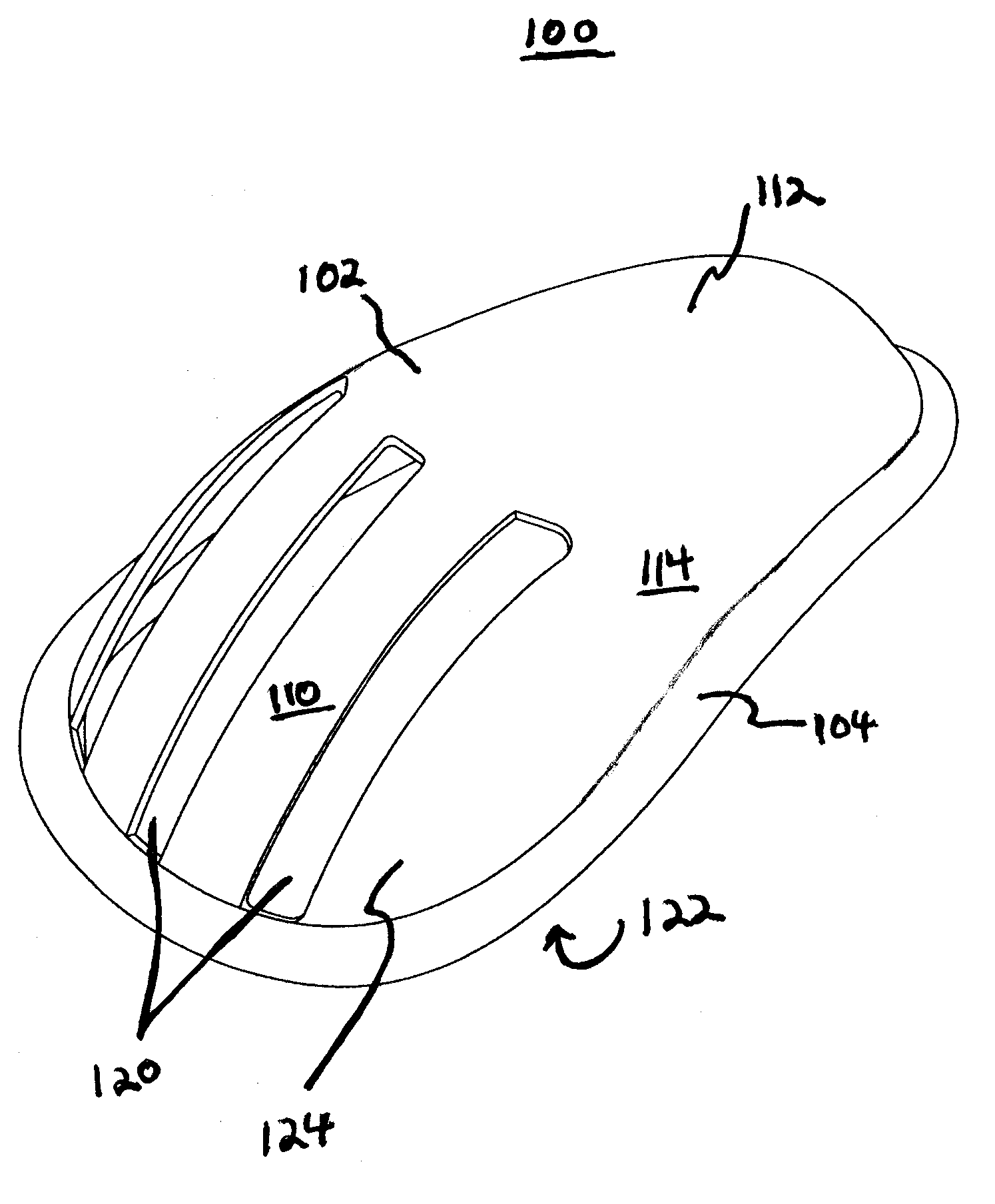
[0031]With reference to FIGS. 1-6, a protective cup 100 according to the present invention comprises cage member 102 and peripheral lip 104.

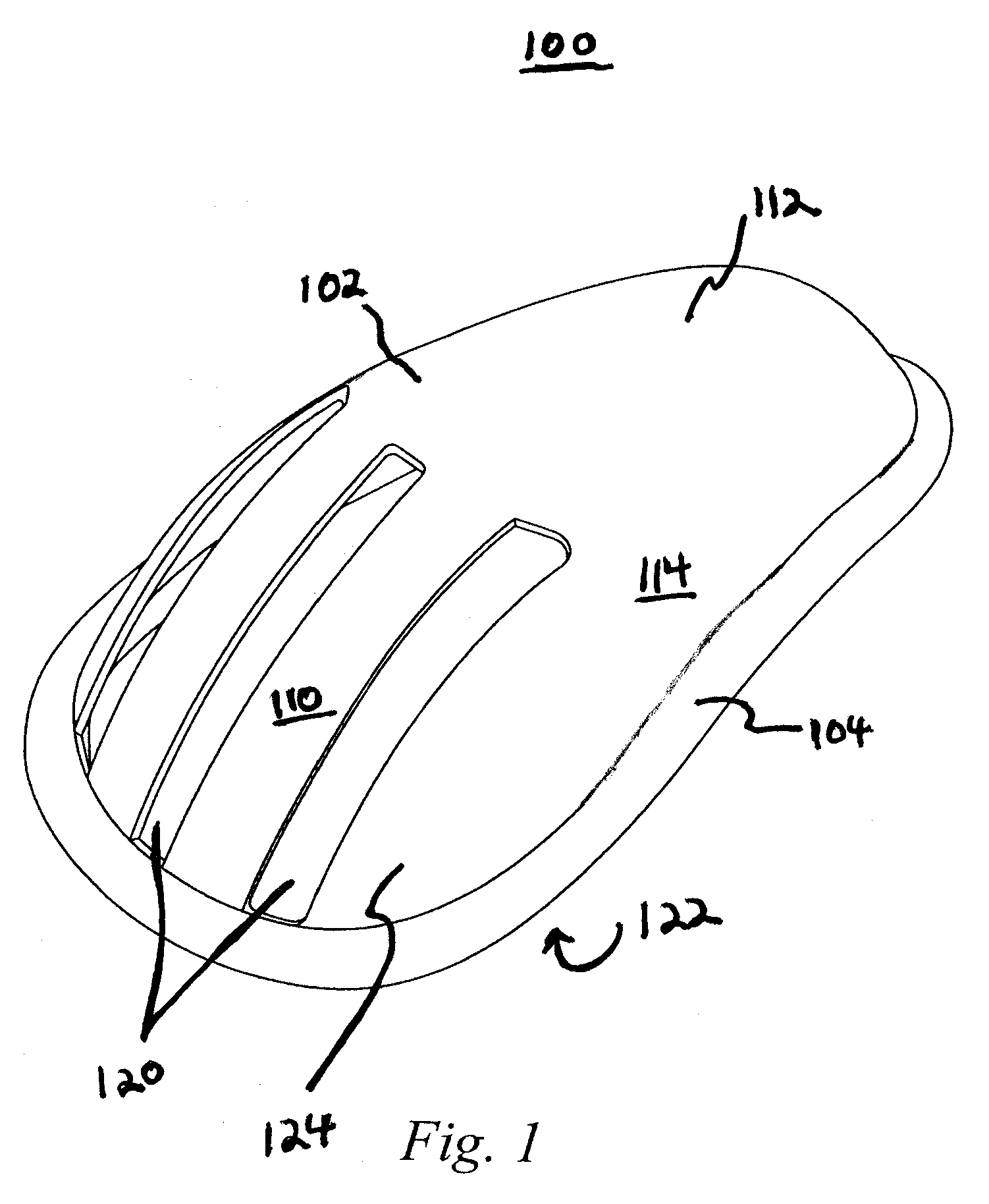
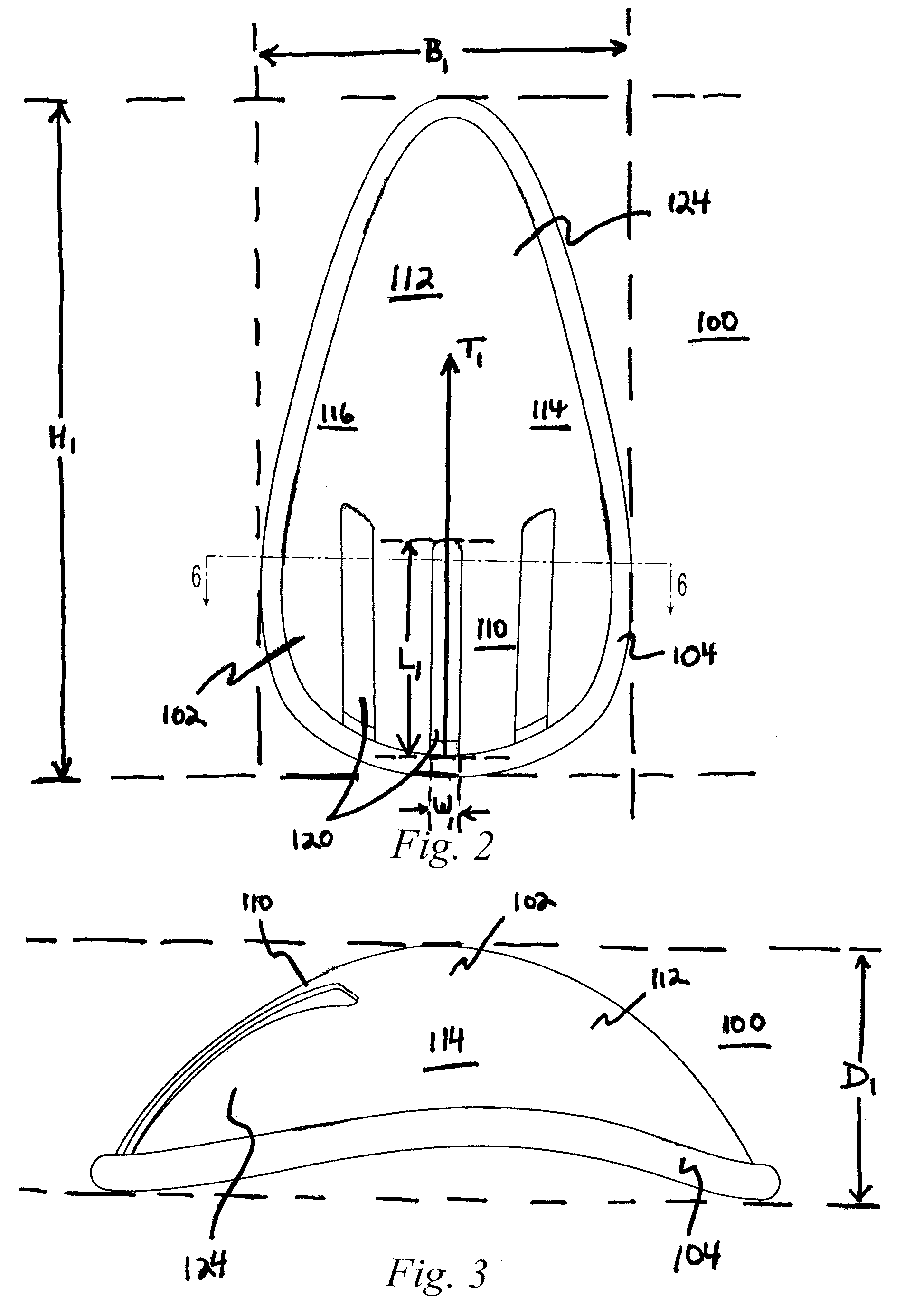
[0032]For a proper fit, the size of protective cup 100 usually varies with the size of the user. FIGS. 2 and 3 define, for example, height H1, breadth B1, and depth D1 for protective cup 100. Protective cup 100 may comprise, for example, a height H1 greater than or equal to about 3 inches and less than or equal to about 12 inches, a breadth B1 greater than or equal to about 2 inches and less than or equal to about 12 inches, and a depth D1 greater than or equal to about 1 inch and less than or equal to about 6 inches; or a height H1 greater than or equal to about 4 inches and less than or equal to about 8 inches, a breadth B1 greater than or equal to about 3 inches and less than or equal to about 6 inches, and a depth D1 greater than or equal to about 2 inches and less than or equal to about 4 inches. However, the actual values of height H1, bre...

second embodiment

[0061]With reference to FIGS. 7-12, a protective cup 200 according to the present invention comprises cage member 202, peripheral lip 204, and linking portions 206 and 208.

[0062]For a proper fit, the size of protective cup 200 usually varies with the size of the user, as discussed with respect to protective cup 100. FIGS. 8 and 9 define, for example, height H2, breadth B2, and depth D2 for protective cup 200. Protective cup 200 may comprise, for example, values of height H2, breadth B2, and depth D2 similar to the values of height H1, breadth B1, and depth D1 for protective cup 100.

[0063]Cage member 202 comprises upper portion 210, lower portion 212, and side portions 214 and 216. Although protective cup 200 may have any desired shape, it may, for example, comprise a concave inner surface 222 and a convex outer surface 224 as shown, for example, in FIGS. 7-12. And, as discussed with respect to protective cup 100, given concave inner surface 222, the centers of gravity of upper porti...

third embodiment

[0081]With reference to FIGS. 13-18, a protective cup 300 according to the present invention comprises cage member 302, peripheral lip 304, and linking portions 306 and 308.

[0082]For a proper fit, the size of protective cup 300 usually varies with the size of the user, as discussed with respect to protective cup 100. FIGS. 14 and 15 define, for example, height H3, breadth B3, and depth D3 for protective cup 300. Protective cup 300 may comprise, for example, values of height H3, breadth B3, and depth D3 similar to the values of height H1, breadth B1, and depth D1 for protective cup 100.

[0083]Cage member 302 comprises upper portion 310, lower portion 312, and side portions 314 and 316. Although protective cup 300 may have any desired shape, it may, for example, comprise a concave inner surface 322 and a convex outer surface 324 as shown, for example, in FIGS. 13-18. And, as discussed with respect to protective cup 100, given concave inner surface 322, the centers of gravity of upper p...


PUM


Abstract

A protective cup includes a cage member and a peripheral lip. The cage member includes upper, lower, and side portions. The upper portion may include a plurality of slots. At least one slot may be oriented so that a direction defined by a largest dimension of the at least one slot extends toward one or more of the lower portion and the side portions. The cup may also include linking portions. The lip is operatively connected to the upper and lower portions. The lip may be operatively connected to the side portions or it may be distanced from the cage member at openings between the lip and side portions. If the lip is distanced from the cage member, the linking portions operatively connect the lip to the side portions to fill the openings or one or more parts of the openings. A method of manufacturing the cup is also disclosed.

Description

BACKGROUND OF THE INVENTION[0001]1. Field of the Invention[0002]Apparatuses and methods consistent with the present invention generally relate to a protective cup and a method of manufacturing the protective cup. The protective cup may be used, for example, in athletic and / or other activities requiring protection for the lower abdominal and / or genital area of men, women, boys, and / or girls.[0003]2. Description of the Related Art[0004]Protective cups have been used for many years by athletes. Traditionally, players in baseball, boxing, football, hockey, lacrosse, and rugby have used such cups to protect themselves from injury resulting from sporting contact with other players (i.e., checking or tackling) and other types of external impact (i.e., getting hit by a pitch or shot). More recently, protective cups have become important in other sports such as martial arts, mountain biking, motocross, snow skiing, waterskiing, and the like. Similarly, in fields such as professional security...

Claims


Application Information

Patent Timeline
IPC IPC(8): A41D13/00
CPCA63B71/1216
Inventor STESZYN, MICHAELLUTHI, SIMON
Owner UNDER ARMOUR
Why Eureka
Try Eureka