Programmable lock having incidental change control

Inactive Publication Date: 2008-11-13
JANAKA PARTNERSHIP
View PDF99 Cites 15 Cited by
  • Summary
  • Abstract
  • Description
  • Claims
  • Application Information

AI Technical Summary

Benefits of technology

[0006]The present invention provides a cylinder lock for operating a bolt, a latch or other closure mechanism, which can be programmed for use with one of a plurality o

Problems solved by technology

In one circumstance of incidental keying, a user key that operates the lock may be used wherein, while being rotated, the key is being pulled axially in the key removal direction, which can cause a raised contour position in an adjacent pin chamber to incidentally or accidentally raise a change ball up into a change member and then into a corresponding retainer cavity when the plug is rotated to the user position.
In another circumstance, an unauthorized user key can have a particular pin position with a contour cut that is slightly hi

Method used


Image

  • Programmable lock having incidental change control
  • Programmable lock having incidental change control
  • Programmable lock having incidental change control

Examples


first embodiment

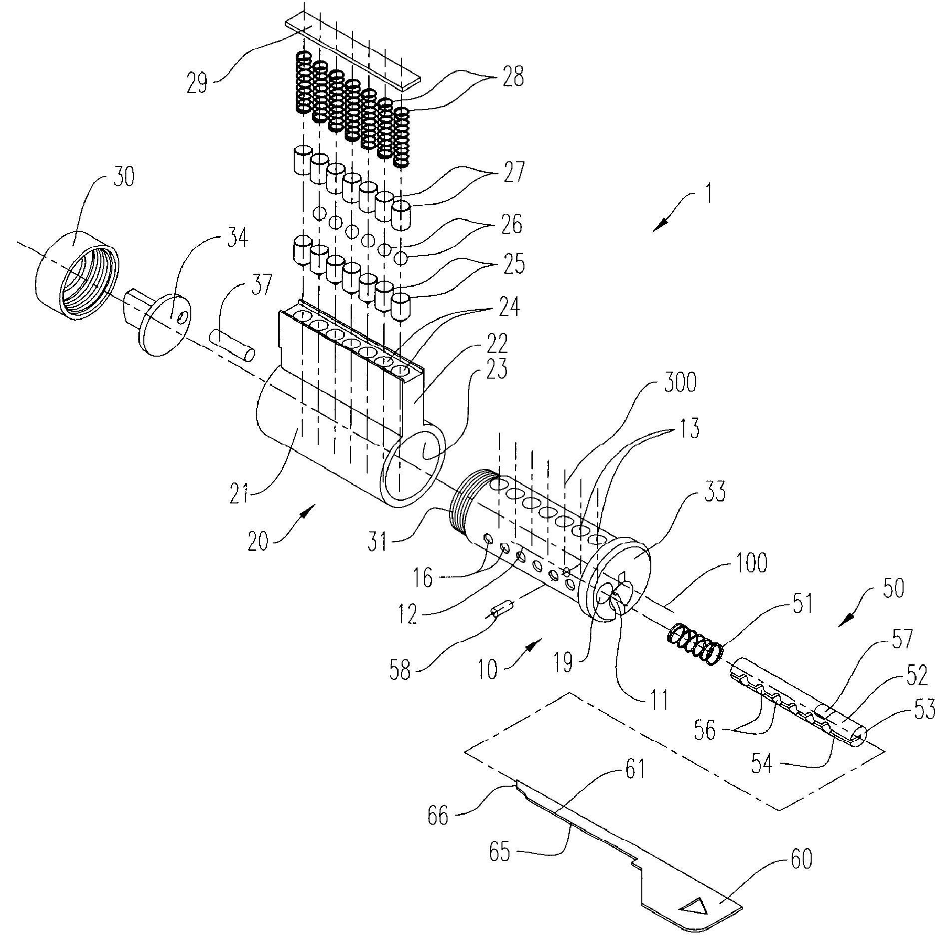
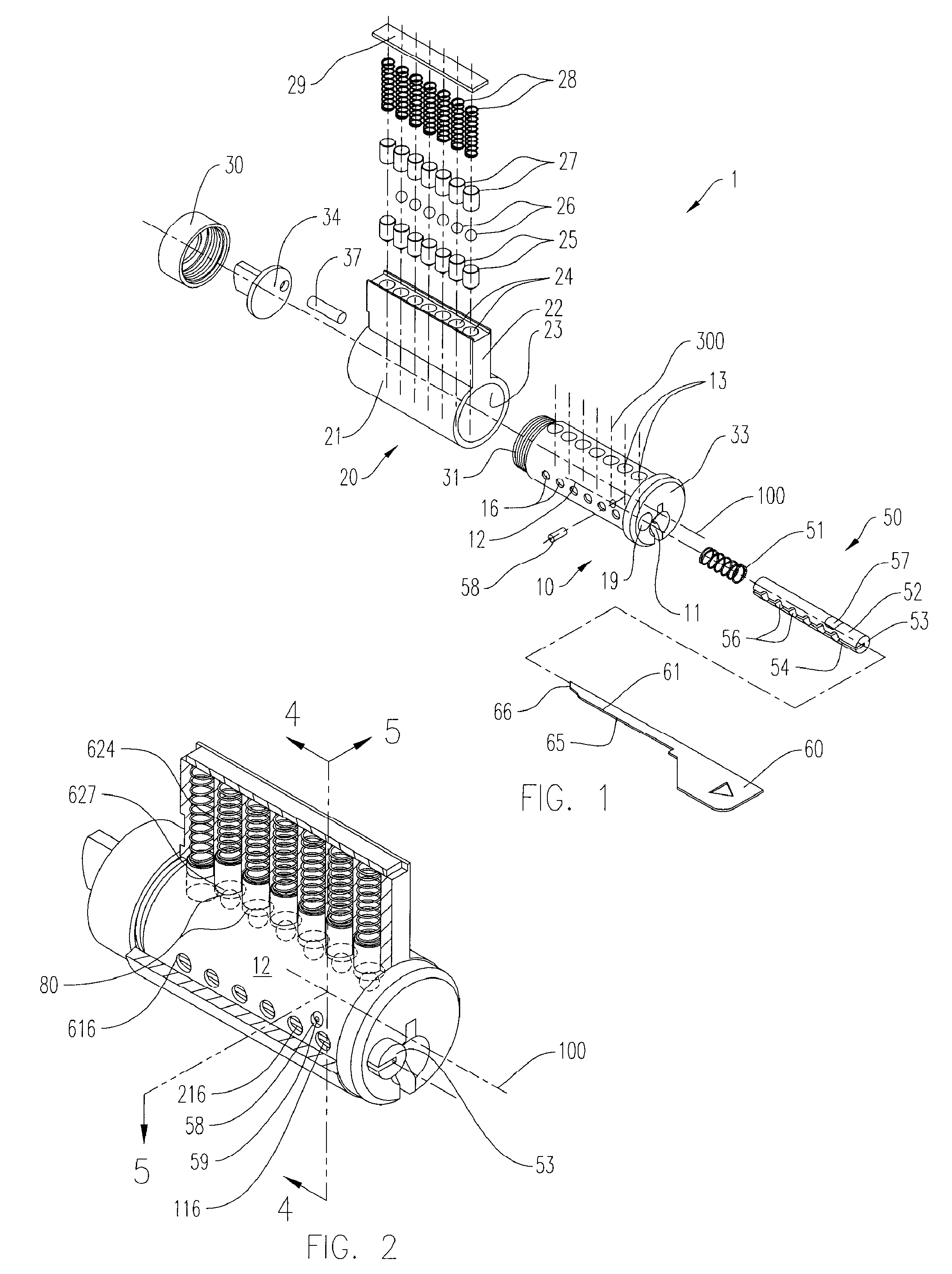
[0072]a programmable lock assembly of the present invention is shown in FIGS. 1 through 28. This embodiment shows a programmable lock assembly that can be programmed to operate with one of a plurality of user keys.

[0073]FIGS. 1 and 2 show the lock assembly that includes a housing 20 having a cylindrical barrel portion 21 and a stack portion 22. The barrel portion 21 has a cylindrical bore that runs through the length of the barrel portion 21 to form an inner surface 23. A plurality of driver chambers 24 are formed along the length of the stack portion 22, and intersect the inner surface 23. The plurality of driver chambers typically includes 5, 6, 7, 8 or 9 such chambers. In the illustrated embodiment, each of the driver chambers 24 has substantially the same diameter, and are aligned transverse to the centerline 100 that passes through the longitudinal center of the barrel portion 21. The plurality of driver chambers 24 corresponding to pin chambers 1 through 7 may be denoted herei...

second embodiment

[0110]In a similar way, the lock of the second embodiment can be reset using the change tool 160 and the operable user key 40 when the lock is configured for operation by the operable user key 40, such as the lock configuration for the second user key 240 shown in FIGS. 27 and 28. In that circumstance, all the change balls 126, 426 and 626 would be raised out of their respective retainer cavities 156 by the inserted change tool 160, while the change balls 226, 326, and 526 are already within their corresponding tumbler chambers 13.

[0111]During normal lock operation and use, the cavity carriage 150 would be positioned in its non-aligned position shown in FIGS. 31 and 32, to avoid incidental keying and accidental reconfiguring of the active change balls disposed in the pin chamber, into their corresponding retainer cavities 156. The cavity carriage 150 would only require rotation to its aligned position, shown in FIGS. 29 and 33, when the user intended to move change members 26 into, ...


PUM


Abstract

A key-operated cylinder lock for operating a bolt or a latch, that can be programmed for use with one of a plurality of user keys without disassembling the lock or replacing the tumblers, with reduction or elimination of incidental or accidental re-keying of the lock. The lock has a rotating plug having one or more retainer cavities formed into the periphery, and lock configuration change balls, movable within the lock between a first position within a driver chamber and a second position within a corresponding retainer cavity when the plug is in a programming position. The positioning of the change balls within either the pin chambers or the retainer cavities determines the key configuration that can operate the lock. The lock employs a means for isolating selectively the retainer cavities from the corresponding driver chambers when the plug is in the programming position, to prevent incidental or accidental movement of the change members from the driver chamber into the retainer cavities.

Description

CROSS-REFERENCE TO RELATED APPLICATIONS[0001]This application claims the benefit of co-pending U.S. Provisional Application No. 60 / 916,367, filed May 7, 2007.BACKGROUND OF THE INVENTION[0002]This invention relates generally to cylinder locks, and more particularly to a programmable cylinder lock that controls changing of the lock configuration, including incidental of accidental configuration changes.[0003]Pin and tumbler locks are known that can operate with one of a set of user keys, and can be reconfigured without disassembling the lock, as disclosed in US patent Publication 2004-0221630, the disclosure of which is incorporated herein by reference. The lock shows a changeable lock assembly with a plug that rotates within a housing, with a series of pins and tumbler, that when aligned at the interface between the plug and the housing, permit rotation of the plug to lock and unlock a latch or catch. One or more change balls are included in the one or more pin chambers, which can mo...

Claims


Application Information

Patent Timeline
IPC IPC(8): E05B27/00
CPCE05B27/005Y10T70/7729Y10T70/7734Y10T70/7605Y10T70/774Y10T70/7746
Inventor HERDMAN, RODRICK A.
Owner JANAKA PARTNERSHIP
Why Eureka
Try Eureka