Accelerator pedal for a vehicle

a technology of accelerator pedals and vehicles, applied in the direction of mechanical control devices, process and machine control, instruments, etc., can solve the problems of insufficiently emulating the tactile response of conventional accelerator pedals or too expensive prior art systems

Inactive Publication Date: 2008-11-13
CTS CORP ELKHART
View PDF31 Cites 60 Cited by
  • Summary
  • Abstract
  • Description
  • Claims
  • Application Information

AI Technical Summary

Benefits of technology

[0013]These and other objects, features and advantages will b

Problems solved by technology

In this regard, prior art systems are either too costly or inadequat

Method used


Image

  • Accelerator pedal for a vehicle
  • Accelerator pedal for a vehicle
  • Accelerator pedal for a vehicle

Examples


Embodiment Construction

[0032]While this invention is susceptible to embodiment in many different forms, this specification and the accompanying drawings disclose several forms as examples of the invention. The invention is not intended to be limited to the embodiments so described, however. The scope of the invention is identified in the appended claims.

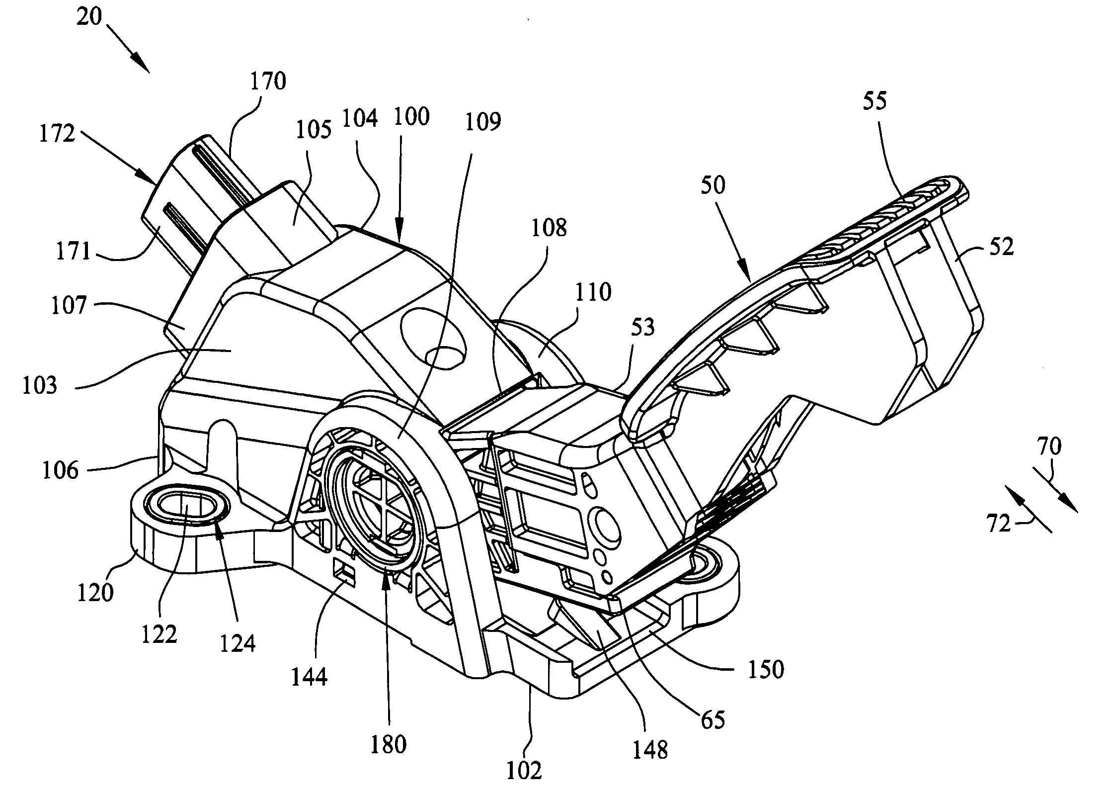
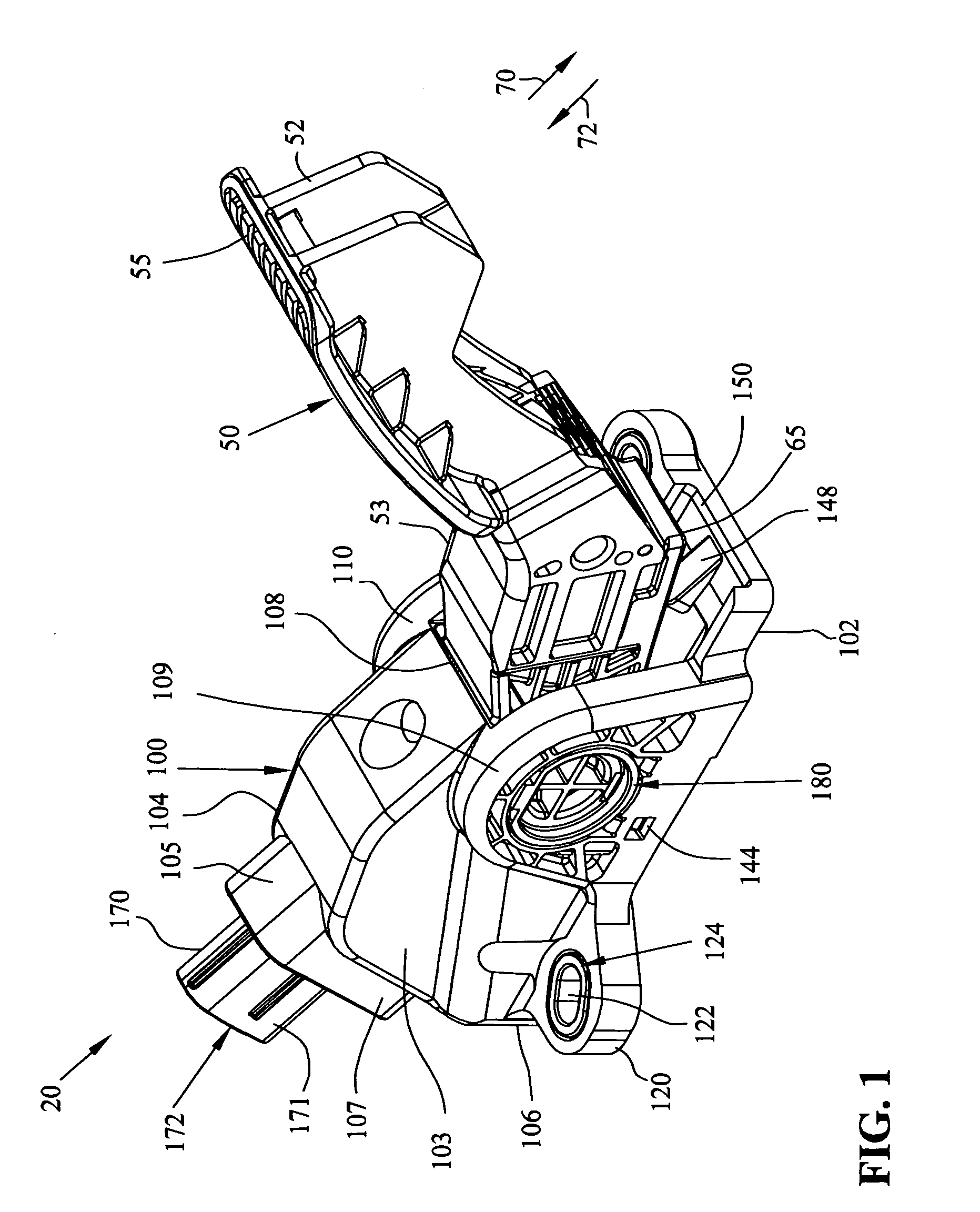
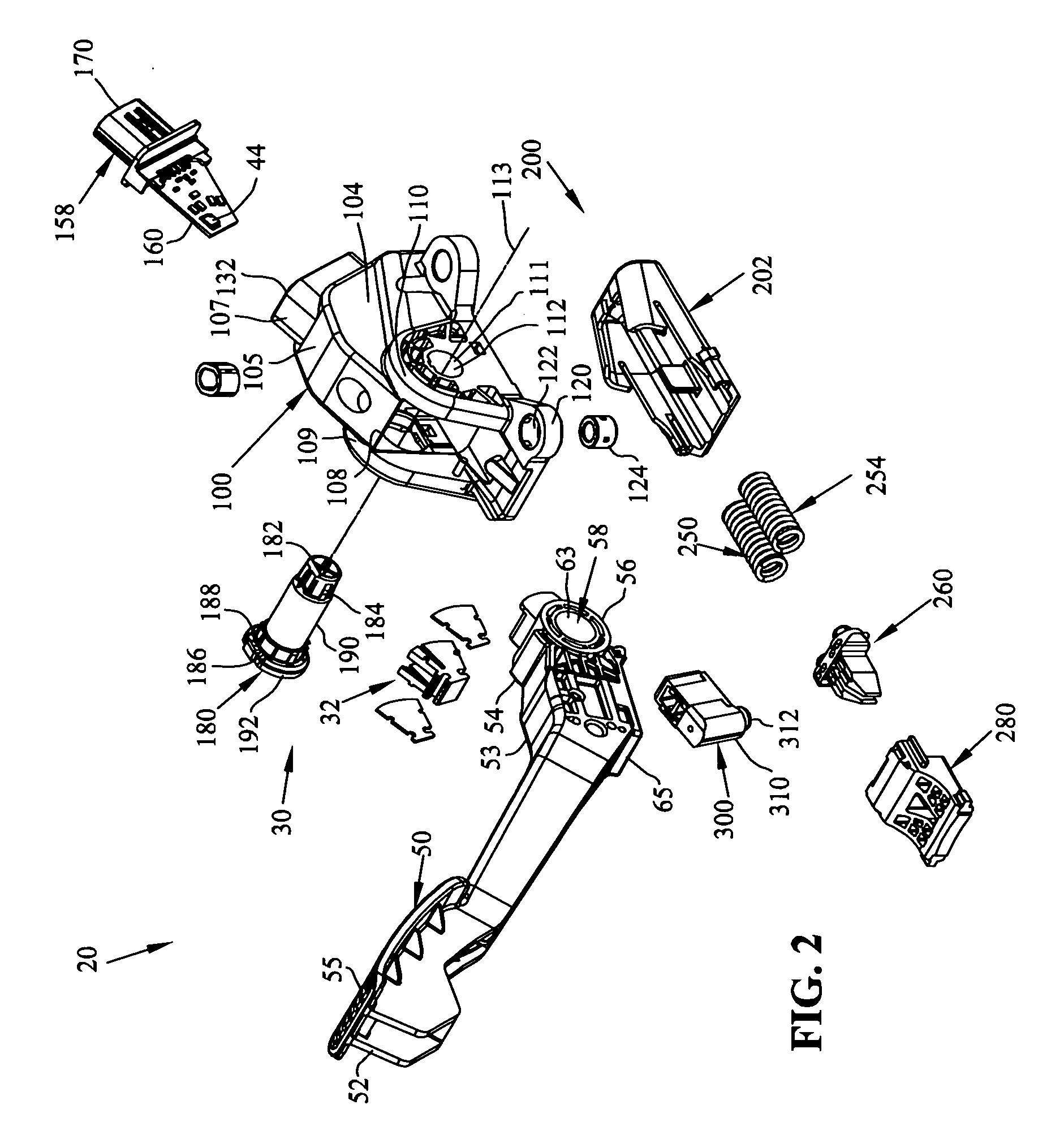
[0033]A non-contacting accelerator pedal assembly 20 according to the present invention is shown in FIGS. 1-6. Pedal assembly 20 includes a pedal housing 100 and a pedal arm 50 that is rotatably mounted to the pedal housing 100. Housing 100 contains the components of the pedal assembly and is adapted for mounting to the firewall or floor of a vehicle (not shown). Housing 100 can be formed from molded plastic.

Pedal Housing

[0034]Pedal housing 100 has a bottom wall 102, side walls 103 and 104, top wall 105, and a front wall 106. Side walls 103 and 104 are generally parallel and opposed and are oriented perpendicular to bottom wall 102 and top wall 105. Severa...


PUM


Abstract

A pedal assembly for a vehicle including a pedal housing and a pedal arm coupled to the housing. A friction generating assembly associated with the housing includes at least an actuator which is engaged by the pedal arm, a brake pad engaged by the actuator, and springs which engage against the brake pad. Arms on the brake pad are adapted to engage with either an interior central wall or interior peripheral wall of the friction generating assembly. In one embodiment, the friction generating assembly defines a separate module which is snap fitted into a cavity defined in the pedal housing. A magnet is coupled to the pedal arm. A sensor is coupled to the pedal housing and positioned in proximity to the magnet. The sensor is responsive to movement of the magnet to generate an electrical signal that is representative of the position of the pedal arm.

Description

CROSS-REFERENCE TO RELATED APPLICATIONS[0001]This application claims the benefit of the filing dates and disclosures of U.S. Provisional Application Ser. No. 60 / 928,430, filed on May 9, 2007; and U.S. Provisional Application Ser. No. 61 / 066,552, filed on Feb. 21, 2008 which are explicitly incorporated herein by reference as are all references cited therein.FIELD OF THE INVENTION[0002]This invention relates to a pedal mechanism. In particular, the pedal may be a vehicle accelerator pedal.BACKGROUND OF THE INVENTION[0003]Automobile accelerator pedals have conventionally been linked to engine fuel subsystems by a cable, generally referred to as a Bowden cable. While accelerator pedal designs vary, the typical return spring and cable friction together create a common and accepted tactile response for automobile drivers. For example, friction between the Bowden cable and its protective sheath otherwise reduce the foot pressure required from the driver to hold a given throttle position. L...

Claims


Application Information

Patent Timeline
IPC IPC(8): G05G1/30
CPCG05G1/38Y10T74/20528G05G5/03B60K26/02G05G1/30
Inventor STEWART, DAVIDKAIJALA, MURRAYMILLER, TAD
Owner CTS CORP ELKHART
Why Eureka
Try Eureka