Protective device plate for an electrical box

a protective device and box technology, applied in the direction of coupling device connection, electrical apparatus casing/cabinet/drawer details, casing/cabinet/drawer details, etc., can solve the problems of lid damage, lid damage to electrical cords connected to electrical devices, and open and closed electrical outlets

a protective device and box technology, applied in the direction of coupling device connection, electrical apparatus casing/cabinet/drawer details, casing/cabinet/drawer details, etc., can solve the problems of lid damage, lid damage to electrical cords connected to electrical devices, and open and closed electrical outlets

US20080277134A1Active Publication Date: 2008-11-13THOMAS & BETTS INT INC

Image

  • Protective device plate for an electrical box
  • Protective device plate for an electrical box
  • Protective device plate for an electrical box

Examples


Embodiment Construction

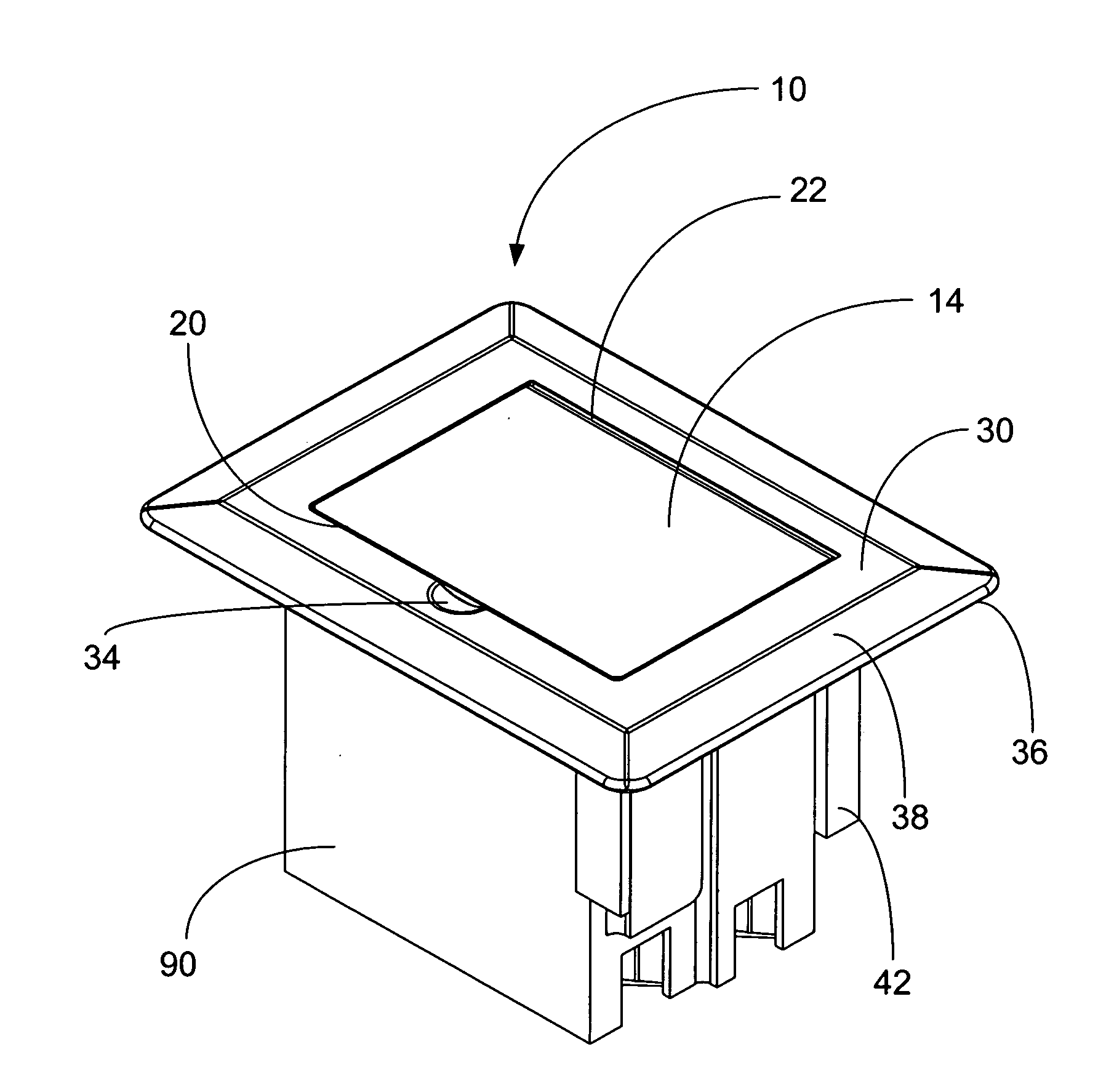
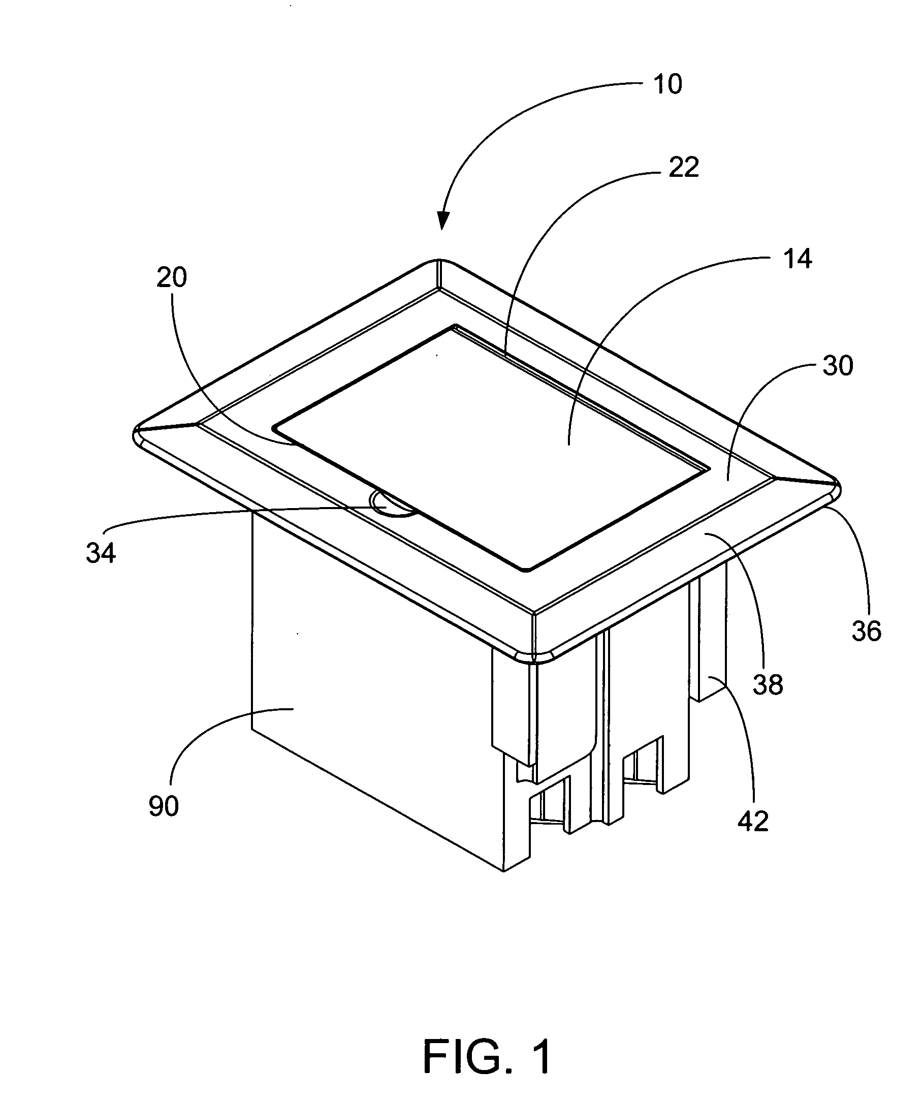
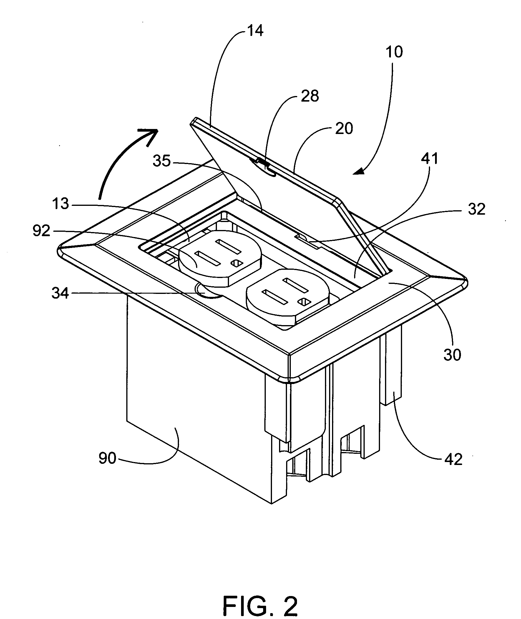
[0027]The present invention is a cover for an electrical box with one or more hide-away lids. The hide-away lids can be retracted below the surface of the face plate of the cover when in the fully open position. The cover can be used with a standard electrical box or it can be integrally molded to a box that has a perimeter side wall extending between a back wall and an open front to define a box interior. Different size boxes with different configurations for housing one or more electrical devices can be used with the cover. Depending on the type of electrical box and the number of electrical devices, the cover can include one or more hide-away lids.

[0028]In a preferred embodiment, the cover includes: a face plate, an elongate slot in the face plate, a lid support structure and a lid. The face plate has a front, a back and an opening with a plurality of sides. Typically, the face plate is substantially flat and has a rectangular shape with sloping side walls that extend downwardly ...


PUM


Abstract

A cover for an electrical box having a face plate, an elongate slot in the face plate, a lid support structure and a lid. The lid fits on the front of the face plate and over the opening and is pivotably movable between an open position, which allows access to the box interior, and a closed position, which prevents access to the box interior. When in the open position, the lid is slidably receivable by the slot and is stored in the lid support structure that extends from the back of the cover.

Description

[0001]This application claims priority from provisional application Ser. No. 60 / 928,832, filed on May 11, 2007, which is incorporated herein in its entirety.FIELD OF THE INVENTION[0002]This invention relates to a cover for an electrical box with a hide-away lid that is concealed within a floor, wall or ceiling so that it is protected from exposure to damage. In particular, the invention relates to a lid that pivotably opens and then slides into a lid support structure located next to the side wall of the electrical box.BACKGROUND OF THE INVENTION[0003]Electrical receptacle boxes installed in a ceiling, a wall or a floor according to a particular need are well known. In general, electrical devices, such as switches and receptacles, are required by electrical codes to be installed in an electrical box. To cover the exposed wiring connections within the box and to give the installation a finished appearance, a cover plate is installed over the electrical device after it is installed in...

Claims


Application Information

Patent Timeline
13 Nov 2008
Publication
US20080277134A1
IPC
H02G3/14
CPC
H02G3/12; H02G3/14
Inventors
JOLLY, ROBERT K.