Liquid discharging device and image forming apparatus

a technology of liquid discharge device and image forming apparatus, which is applied in printing and other directions, can solve the problems of ink drop not being properly discharged from the nozzle, nozzle clogging, and blade clogging

Inactive Publication Date: 2008-11-13
RICOH KK
View PDF3 Cites 33 Cited by
  • Summary
  • Abstract
  • Description
  • Claims
  • Application Information

AI Technical Summary

Benefits of technology

[0008]This patent specification describes a novel liquid discharging device. One example of a novel liquid discharging device includes a liquid discharging head and a maintenance-recovery mechanism. The liquid discharging head is configured to discharge a liquid drop, and includes a plurality of discharge openings arranged to form a row of discharge openings on a discharge opening surface. The maintenance-recovery mechanism is configured to maintain and recover a condition of the liquid discharging head, and includes a blade, a belt, and a pressing member. The blade is configured to wipe the discharge opening surface of the liquid discharging head. The belt is configured to carry the blade in a direction of rotation along the row of discharge openings. The pressing member is configured to press an inner circumferential surface of the belt to move a portion of the belt opposing the liquid discharging head toward the liquid discharging head to maintain a substantially constant gap between the blade and the discharge opening surface of the liquid discharging head. The gap has a length in the direction of rotation of the belt not smaller than a length of the row of discharge openings and not greater than a length of the liquid discharging head.
[0009]This patent specification further describes a novel image forming apparatus. One example of a novel image forming apparatus forms an image on a recording medium, and includes a liquid discharging device including a liquid discharging head and a maintenance-recovery mechanism. The liquid discharging head is configured to discharge a liquid drop onto a recording medium, and includes a plurality of discharge openings arranged to form a row of discharge openings on a discharge opening surface. The maintenance-recovery mechanism is configured to maintain and recover a condition of the liquid discharging head, and includes a blade, a belt, and a pressing member. The blade is configured to wipe the discharge opening surface of the liquid discharging head. The belt is configured to carry the blade in a direction of rotation along the row of discharge openings. The pressing member is configured to press an inner circumferential surface of the belt to move a portion of the belt opposing the liquid discharging head toward the liquid discharging head to maintain a substantially constant gap between the blade and the discharge opening surface of the liquid discharging head. The gap has a length in the direction of rotation of the belt not smaller than a length of the row of discharge openings and not greater than a length of the liquid discharging head.

Problems solved by technology

When ink having an increased viscosity, dried ink, or a foreign substance (e.g., dust) is adhered to an outer surface of the nozzle, the nozzle may be clogged.
Similarly, when air bubbles are generated inside the nozzle, an ink drop may not be properly discharged from the nozzle.
However, such a long belt may be warped by gravity, and therefore the blade may not wipe a liquid discharging surface of the long, liquid discharging head by applying constant pressure on the liquid discharging surface.

Method used


Image

  • Liquid discharging device and image forming apparatus
  • Liquid discharging device and image forming apparatus
  • Liquid discharging device and image forming apparatus

Examples


Embodiment Construction

[0038]In describing, exemplary embodiments illustrated in the drawings, specific terminology is employed for the sake of clarity. However, the disclosure of this patent specification is not intended to be limited to the specific terminology so selected and it is to be understood that each specific element includes all technical equivalents that operate in a similar manner.

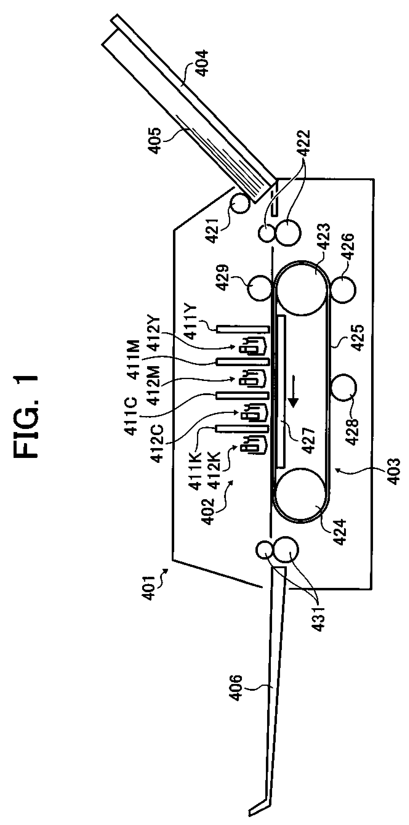
[0039]Referring now to the drawings, wherein like reference numerals designate identical or corresponding parts throughout the several views, in particular to FIG. 1, an image forming apparatus 401 according to an exemplary embodiment is explained.

[0040]As illustrated in FIG. 1, the image forming apparatus 401 includes a paper tray 404, a feeding roller 421, a sheet supply roller pair 422, an image forming device 402, a conveying mechanism 403, an output roller pair 431, and an output tray 406. The image forming device 402 includes line-type recording heads 411Y, 411M, 411C, and 411K and maintenance-recovery units ...


PUM


Abstract

A liquid discharging device includes a liquid discharging head and a maintenance-recovery mechanism. In the liquid discharging head, a row of discharge openings is formed on a discharge opening surface. In the maintenance-recovery mechanism, a blade wipes the discharge opening surface. A belt carries the blade in a direction of rotation along the row of discharge openings. A pressing member presses an inner circumferential surface of the belt to move a portion of the belt opposing the liquid discharging head toward the liquid discharging head to maintain a substantially constant gap between the blade and the discharge opening surface. The gap has a length in the direction of rotation of the belt not smaller than a length of the row of discharge openings and not greater than a length of the liquid discharging head.

Description

TECHNICAL FIELD[0001]The present specification describes a liquid discharging device and an image forming apparatus, and more particularly, a liquid discharging device and an image forming apparatus for discharging liquid onto a recording medium to form an image on the recording medium.DISCUSSION OF THE BACKGROUND[0002]An image forming apparatus, such as a copying machine, a printer, a facsimile machine, a plotter, or a multifunction printer having two or more of copying, printing, scanning, and facsimile functions, forms an image on a recording medium (e.g., a sheet) by discharging liquid. For example, the image forming apparatus includes a liquid discharging device for discharging liquid (e.g., an ink drop) onto a conveyed sheet. The ink drop is adhered to the sheet to form an image on the sheet. The liquid discharging device includes a liquid discharging head (e.g., a recording head) including a nozzle. The ink drop is discharged from the nozzle.[0003]When ink having an increased...

Claims


Application Information

Patent Timeline
Patent Type & Authority Applications(United States)
IPC IPC(8): B41J2/165
CPCB41J2/16538B41J2/16552B41J2/16585B41J2/16541
Inventor TOKUNO, TOSHIROH
Owner RICOH KK
Why Eureka
Try Eureka