Method and apparatus for minimizing inclusions in a glass making process

a glass making process and inclusion technology, applied in glass rolling apparatus, glass tempering apparatus, manufacturing tools, etc., can solve the problems of secondary zircon crystals becoming more pronounced, and ultimately affecting the quality of glass

Active Publication Date: 2008-11-20
CORNING INC
View PDF14 Cites 55 Cited by
  • Summary
  • Abstract
  • Description
  • Claims
  • Application Information

AI Technical Summary

Benefits of technology

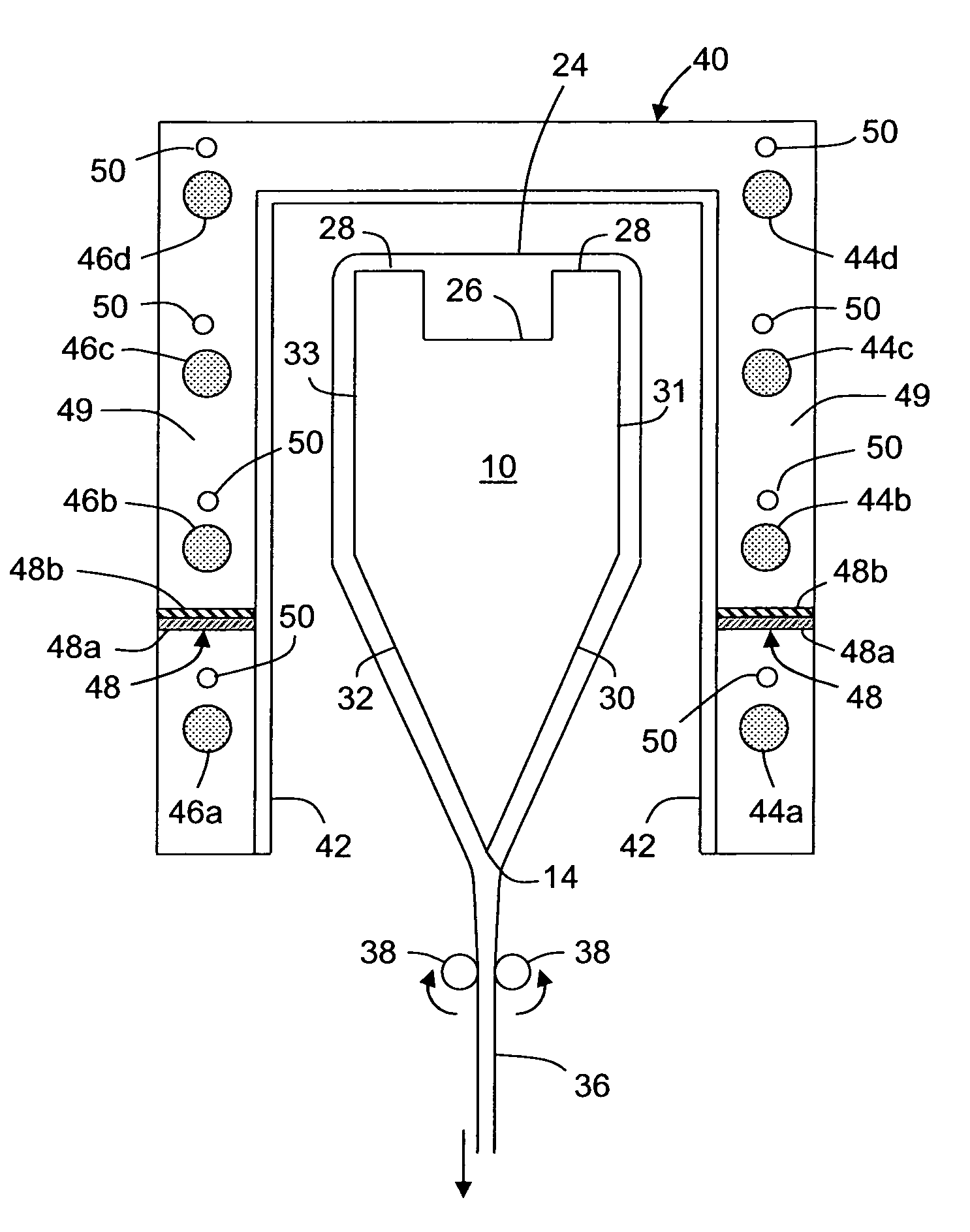
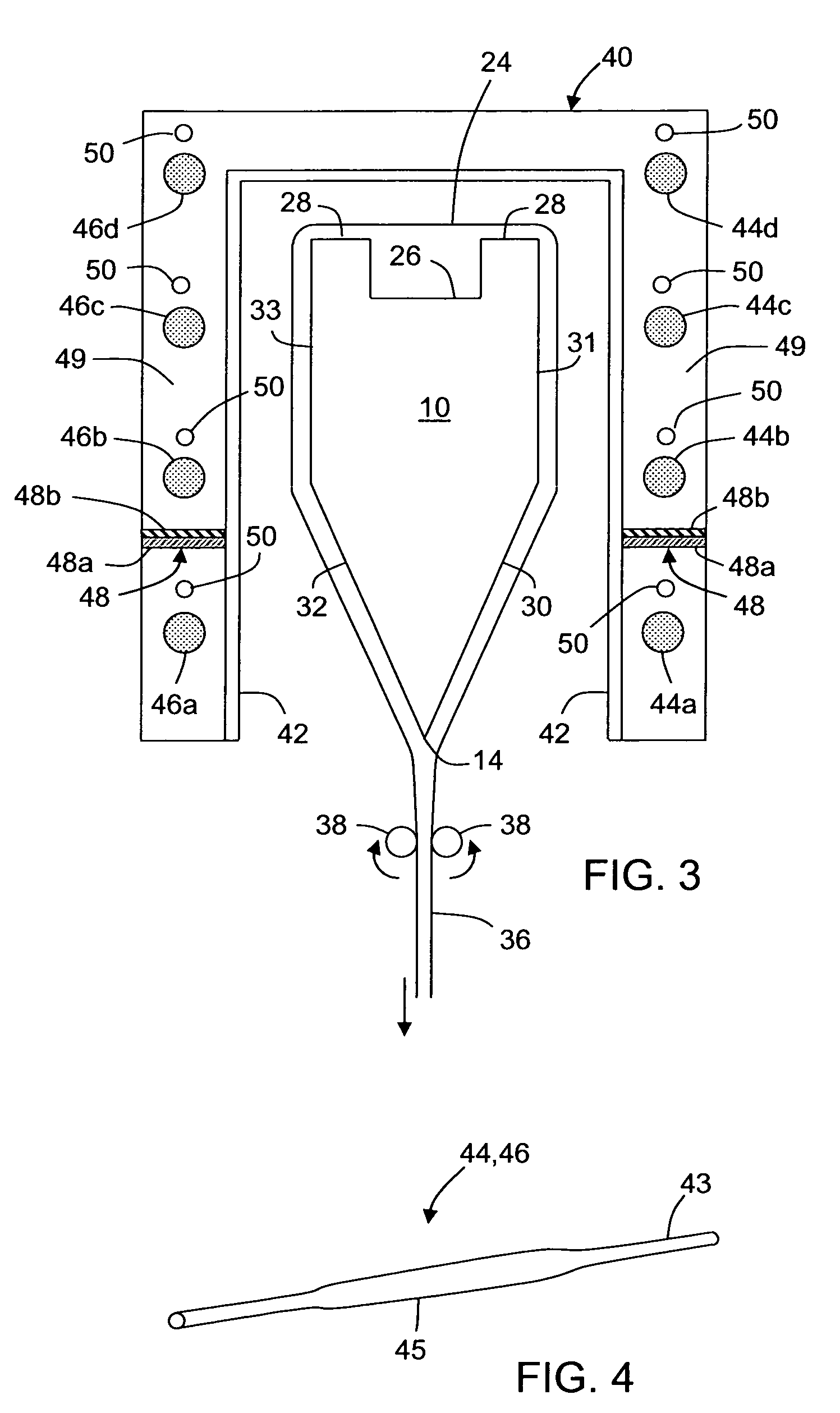
[0015]In still another embodiment, a method of making a glass sheet is disclosed comprising flowing a molten glass over a forming body comprising converging forming surfaces, forming a vertical temperature gradient between a temperature T1 at the top of the forming body and a temperature T2 at the bottom of the forming body, drawing the molten glass from the bottom of the forming body to form a glass sheet, and wherein the temperature T2 at the bottom of the forming body is substantially decoupled from the temperature T1 at the top of the forming body such that a change in T2 does not cause a substantial change in T1.

Problems solved by technology

An isopipe used in the fusion process is subjected to high temperatures and substantial mechanical loads as molten glass flows into its trough and over its outer surfaces.
A source of losses in the manufacture of sheet glass for use as LCD substrates is the presence of zircon crystal inclusions (referred to herein as “secondary zircon crystals” or “secondary zircon defects”) in the glass as a result of the glass' passage into and over the zircon isopipe used in the manufacturing process.
The problem of secondary zircon crystals becomes more pronounced with devitrification-sensitive glasses which need to be formed at higher temperatures.
In particular, these defects ultimately arise as a result of zirconia (i.e., ZrO2 and / or Zr+4+2O−2) dissolving into the molten glass at the temperatures and viscosities that exist in the isopipe's trough and along the upper walls (weirs) on the outside of the isopipe.
Eventually these crystals grow long enough to break off into the glass flow and become defects at or near the fusion line of the sheet.
Moreover, if the temperature of the glass at the isopipe root is too low, devitrification of the glass may occur.
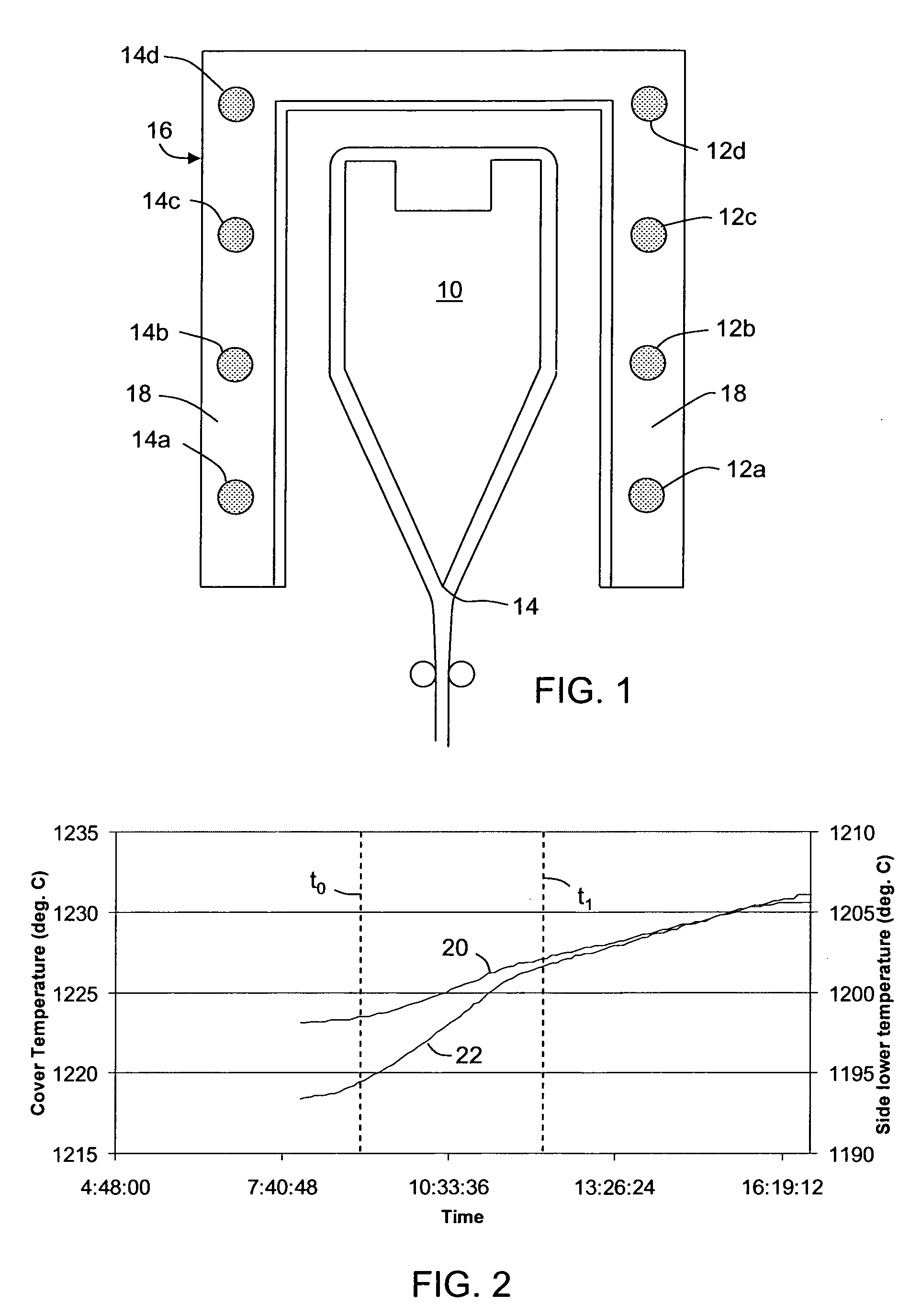
Unfortunately, raising the temperature near the root of the isopipe has had the unpleasant effect of also increasing the temperature of the molten glass within the isopipe trough, decreasing the viscosity of the glass and hence impacting the mass flow distribution of the glass.

Method used


Image

  • Method and apparatus for minimizing inclusions in a glass making process
  • Method and apparatus for minimizing inclusions in a glass making process
  • Method and apparatus for minimizing inclusions in a glass making process

Examples


example 1

[0057]Shown in FIG. 11 are additional modeling data showing the predicted difference for the formation of precipitated zircon for a base case without a barrier (curve 600) and the case with an insulating thermal barrier between the bottom-most heating elements and the next vertically adjacent heating element (curve 602). The glass flow was assumed to be about 1500 pounds per hour. Isopipe temperatures at the weir, break and root for the base case, depicted by curve 600, were 1232° C., 1213° C. and 1153° C., respectively. The same temperatures with the insulating thermal shield (weir, break and root), depicted by curve 602, were 1228° C., 1205° C. and 1159° C., respectively. Precipitated zircon crystals (“secondary” zircon) form on the isopipe as a result of the supersaturation of ZrO2 at the isopipe-glass interface as the glass melt flows over the isopipe. To determine the presence of supersaturation, it is necessary to know the ZrO2 concentration profile in the glass melt and to co...

example 2

[0058]Shown in FIG. 12 is a chart plotting on the left hand axis power supplied to heating elements in kW, on the right hand axis the temperature differential between the weirs and the root, and along the bottom axis (x axis) time in hours for a conventional isopipe and enclosure. Four curves are shown: three curves representing the power supplied to three heating zones; one heating zone below the root (the “transition” zone), a lower muffle heating zone proximate the root (i.e. the “bottom-most” heating element as used herein, e.g. 12a), and an upper muffle heating zone (heaters above the bottom-most heating element, e.g. 12b, c and d). These curves are respectively referenced as curves 700, 702 and 704. Fourth curve 706 represents the temperature differential between the weirs and root of the isopipe.

[0059]Shown in FIG. 13 is a chart plotting on the left hand axis power supplied to heating elements in kW, on the right hand axis the temperature differential between the weirs and th...


PUM

PropertyMeasurementUnit
temperatureaaaaaaaaaa
thicknessaaaaaaaaaa
temperatureaaaaaaaaaa

Abstract

An apparatus for forming a glass sheet with reduced zircon inclusions in the glass sheet is disclosed. In one embodiment, the apparatus comprises heating elements distributed vertically between the weirs of a forming wedge and the root of the forming wedge, and wherein a thermal barrier is disposed between adjacent heating elements. A method of using the apparatus is also disclosed.

Description

CROSS-REFERENCE TO RELATED APPLICATIONS[0001]This application claims the benefit of priority under 35 U.S.C. § 119(e) of U.S. Provisional Application Ser. No. 60 / 930,765 filed on May 18, 2007.BACKGROUND OF THE INVENTION[0002]1. Field of the Invention[0003]This invention relates to fusion processes for producing sheet glass and, in particular, to fusion processes which employ a crystalline ceramic isopipe. Even more particularly, the invention relates to controlling the formation of crystalline defects in sheet glass produced by fusion processes employing ceramic containing isopipes. The techniques of the invention are particularly useful when fusion processes are employed to produce glass sheets for use as substrates in the manufacture of liquid crystal displays, e.g., AMLCDs[0004]2. Technical Background[0005]The fusion process is one of the basic techniques used in the glass making art to produce sheet glass. Compared to other processes known in the art, e.g., the float and slot dr...

Claims


Application Information

Patent Timeline
Patent Type & Authority Applications(United States)
IPC IPC(8): C03B17/06
CPCC03B17/064C03B17/06
Inventor FILIPPOV, ANDREY V.HE, CHUNHONG (CHELSIE) C.KOCATULUM, BULENTMORSE, KATHLEEN ELIZABETHWANG, LIMING
Owner CORNING INC
Why Eureka
Try Eureka