Rough hew planer

a rough hewn and planer technology, applied in the direction of mechanical surface treatment, metal sawing apparatus, sawing apparatus, etc., can solve the problems of plurality of random hew or adz marks distributed across and along the log, less desirable techniques for some purchasers, and inability to preserve the look of rough hewn logs

Inactive Publication Date: 2008-11-27
JANZEN MARTIN
View PDF12 Cites 11 Cited by
  • Summary
  • Abstract
  • Description
  • Claims
  • Application Information

AI Technical Summary

Benefits of technology

[0011]The bottom shoe may comprise a front shoe having a front surface locatable ahead of the cutter head in a direction of travel of the hand planer and a rear shoe having a rear surface locatable behind the cutter head in a direction of travel of the hand planer. The rear surface may include a planar portion located proximate to the cutter head when the rear shoe may be secured to the hand planer.

Problems solved by technology

While more efficient, such techniques also are less desirable to some purchasers who prefer the look of logs prepared using traditional methods such as hewing or utilizing an adz which results in a plurality of random hew or adz marks distributed across and along the log.
Previous attempts to preserve the look of a rough hewn log have not been satisfactory.
Such an attachment will produce regularly spaced apart marks which do not accurately replicate the desired random appearance of hew marks.
Work pieces resulting from these devices will not therefore have a satisfactory hand hewn appearance.

Method used


Image

  • Rough hew planer
  • Rough hew planer
  • Rough hew planer

Examples


Embodiment Construction

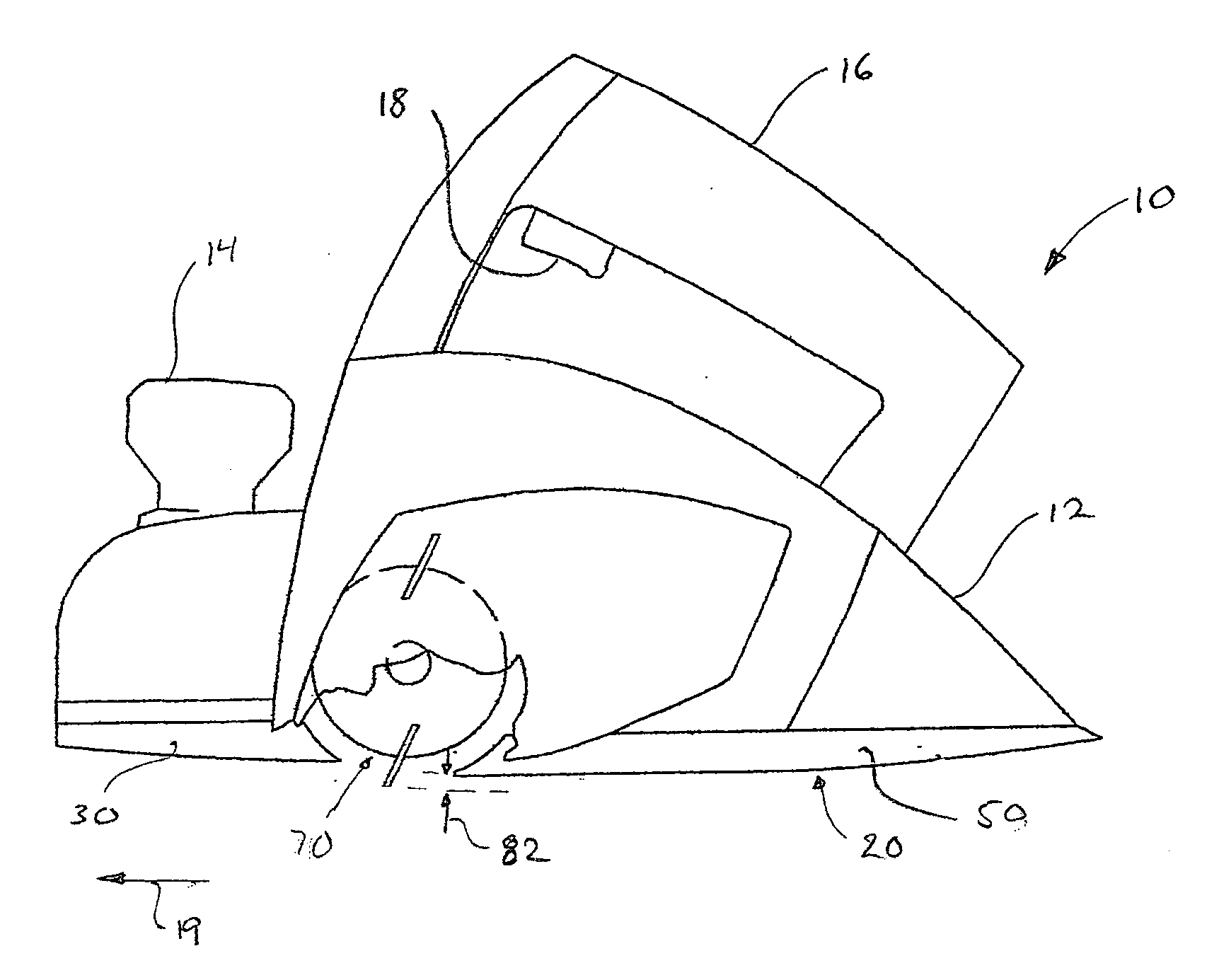
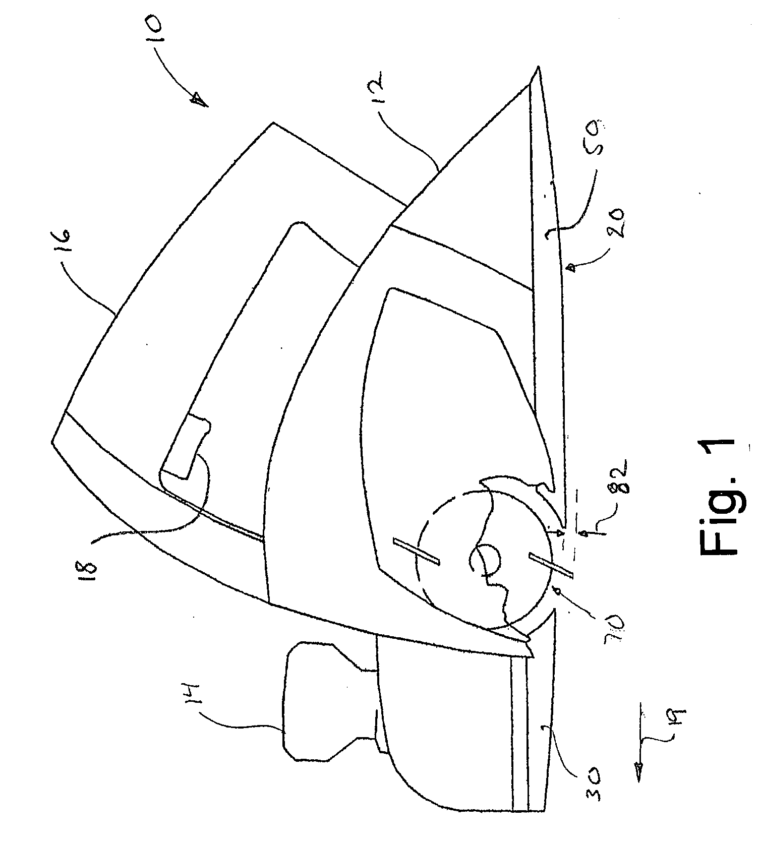
[0022]Referring to FIG. 1, an apparatus according to a first embodiment of the invention is shown generally at 10. The apparatus comprises a hand planer 12 having a curved bottom 20 and a rotatable transverse cutter rotor 70 therein. The hand planer 12 is of a conventional type and includes an electric motor (not shown) and first and second handles 14 and 16, respectively. The second handle includes a power button or trigger 18 for energizing the motor so as to rotate the cutter rotor 70. The hand planer 12 is translatable in a forward direction indicated generally at 19 so as to finish the surface of a wood workpiece.

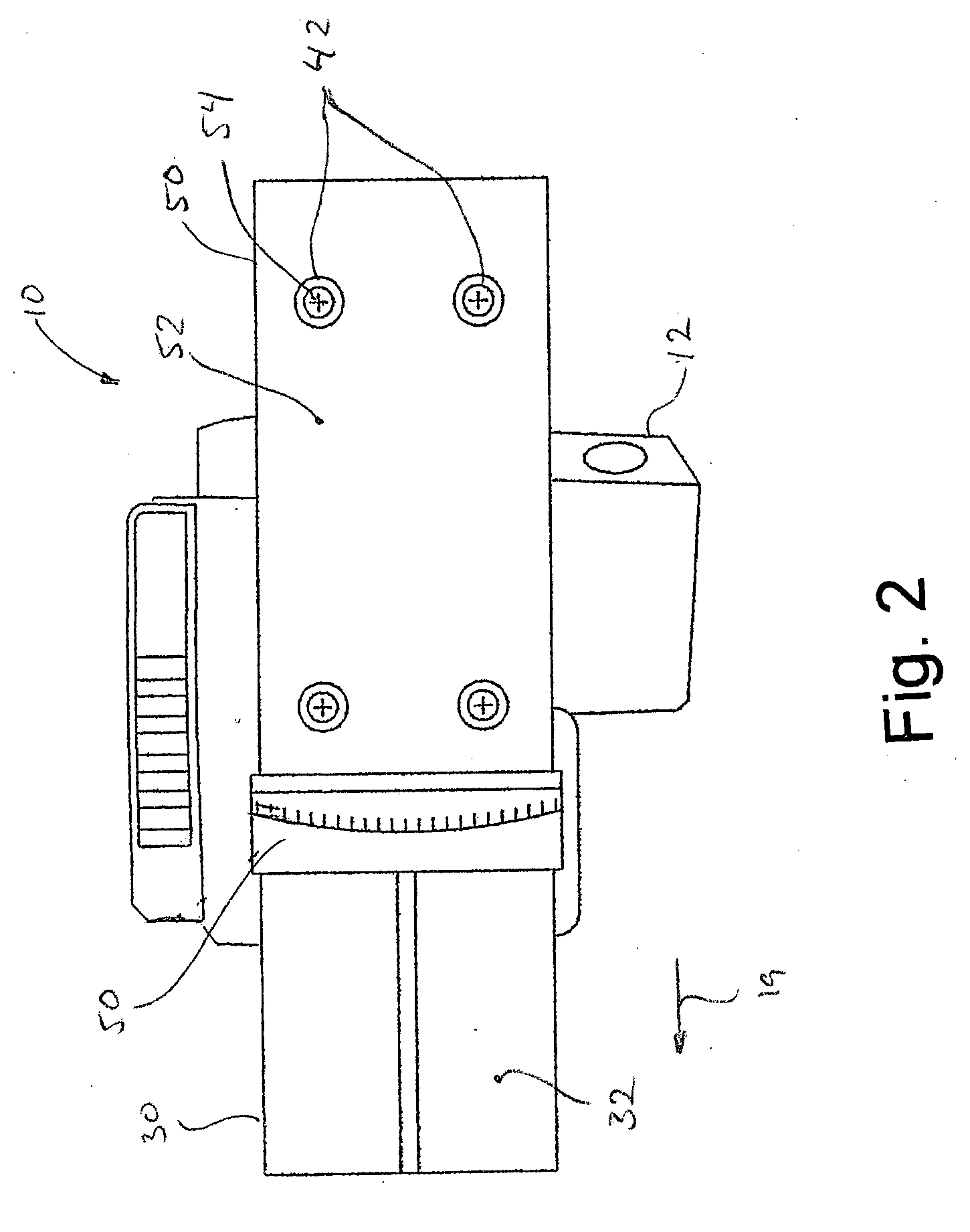
[0023]The hand planer 12 includes a front bottom shoe 30 and a rear bottom shoe 50 attached to the bottom thereof. The front and rear bottom shoes 30 and 50 may be formed integrally with the hand planer 12 or may optionally be securable to the bottom of the hand planer 12 by means of screws 54 or other suitable fasteners as are known in the art. It will be appreciated ...


PUM

PropertyMeasurementUnit
lengthaaaaaaaaaa
shapeaaaaaaaaaa
depthaaaaaaaaaa

Abstract

Disclosed is a method and apparatus finishing the surface of a wood piece to appear rough hewn. The apparatus comprises a hand planer having a longitudinal direction, a rotatable cutter head having at least one planning blade and a bottom surface. The bottom surface has a convex curved profile longitudinally along the hand planer. The cutter head extends below the curved profile of the bottom surface. The method comprises simultaneously translating and rocking the hand planer on the bottom surface so as to intermittently engage the cutter head against a surface so as to form a plurality of spaced apart divots therein.

Description

FIELD OF THE INVENTION[0001]This invention relates to the field of devices and methods for finishing of logs in general and in particular to a method and apparatus for surface finishing a log to appear rough hewn.BACKGROUND OF THE INVENTION[0002]Log homes are well known and have remained popular over the years. The use of logs for constructing homes and other buildings requires that the bark and branches be removed. Advances in log processing has allowed raw logs to be processed more quickly than previously and with less man power than by using previous hand processing methods. Many of these now conventional techniques, such as milling, for example, not only remove the bark and branches but also render the resulting log substantially uniform in shape. While more efficient, such techniques also are less desirable to some purchasers who prefer the look of logs prepared using traditional methods such as hewing or utilizing an adz which results in a plurality of random hew or adz marks ...

Claims


Application Information

Patent Timeline
Patent Type & Authority Applications(United States)
IPC IPC(8): B27C5/10B27G13/12B27G17/02
CPCB27C1/10B27M1/003
Inventor JANZEN, MARTIN
Owner JANZEN MARTIN
Why Eureka
Try Eureka