Bird feeder
- Summary
- Abstract
- Description
- Claims
- Application Information
AI Technical Summary
Benefits of technology
Problems solved by technology
Method used
Image

Examples
first embodiment
[0056]the present invention is illustrated in FIGS. 1-18. In this embodiment the base is removably supported from the feed container. The base is removable by means of a set of latch fingers that are depressed in a radial direction to release the base from the bottom end of the feed container. The embodiment of FIGS. 1-18 also illustrates the construction of the interconnecting member that is used for connecting together the separate port members. The preferred embodiment of the interconnecting matter is illustrated in FIGS. 11 and 12.
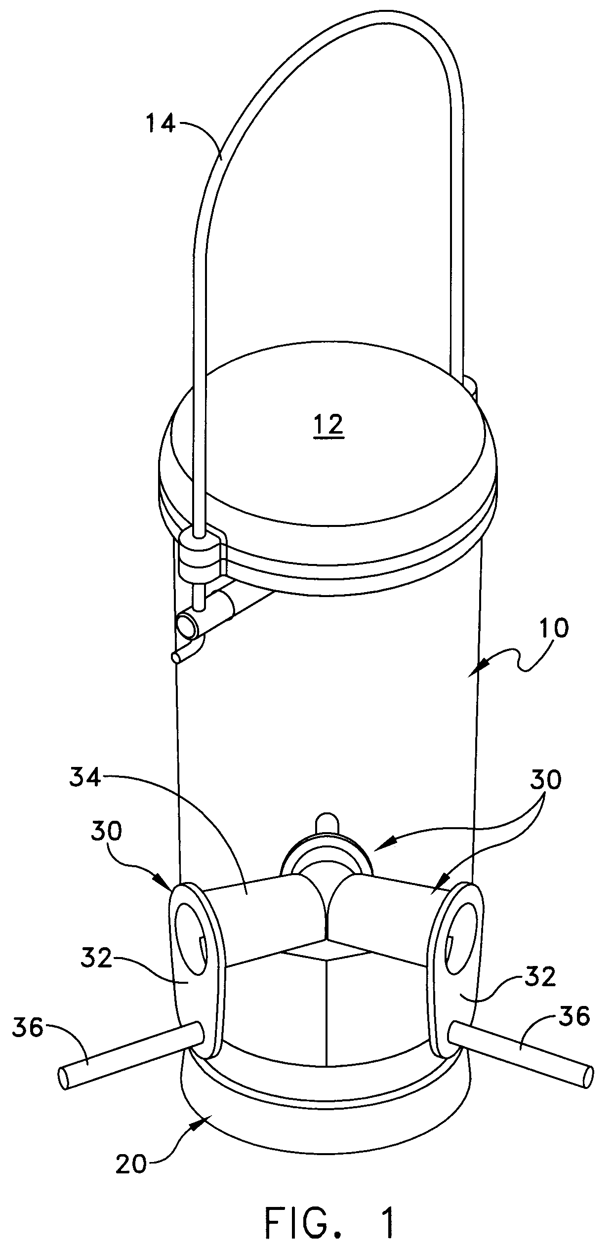
[0057]Reference is now made to FIG. 1 which is a perspective view of a bird feeder constructed in accordance with the principles of the present invention. This feeder includes a container or holder 10 that is preferably constructed of a clear plastic material. The container 10 holds the bird seed or other type of bird feed. The container 10 is open at its top and bottom. A top or cover 12 is supported over the top end of the container 10. The top 12 ma...
second embodiment
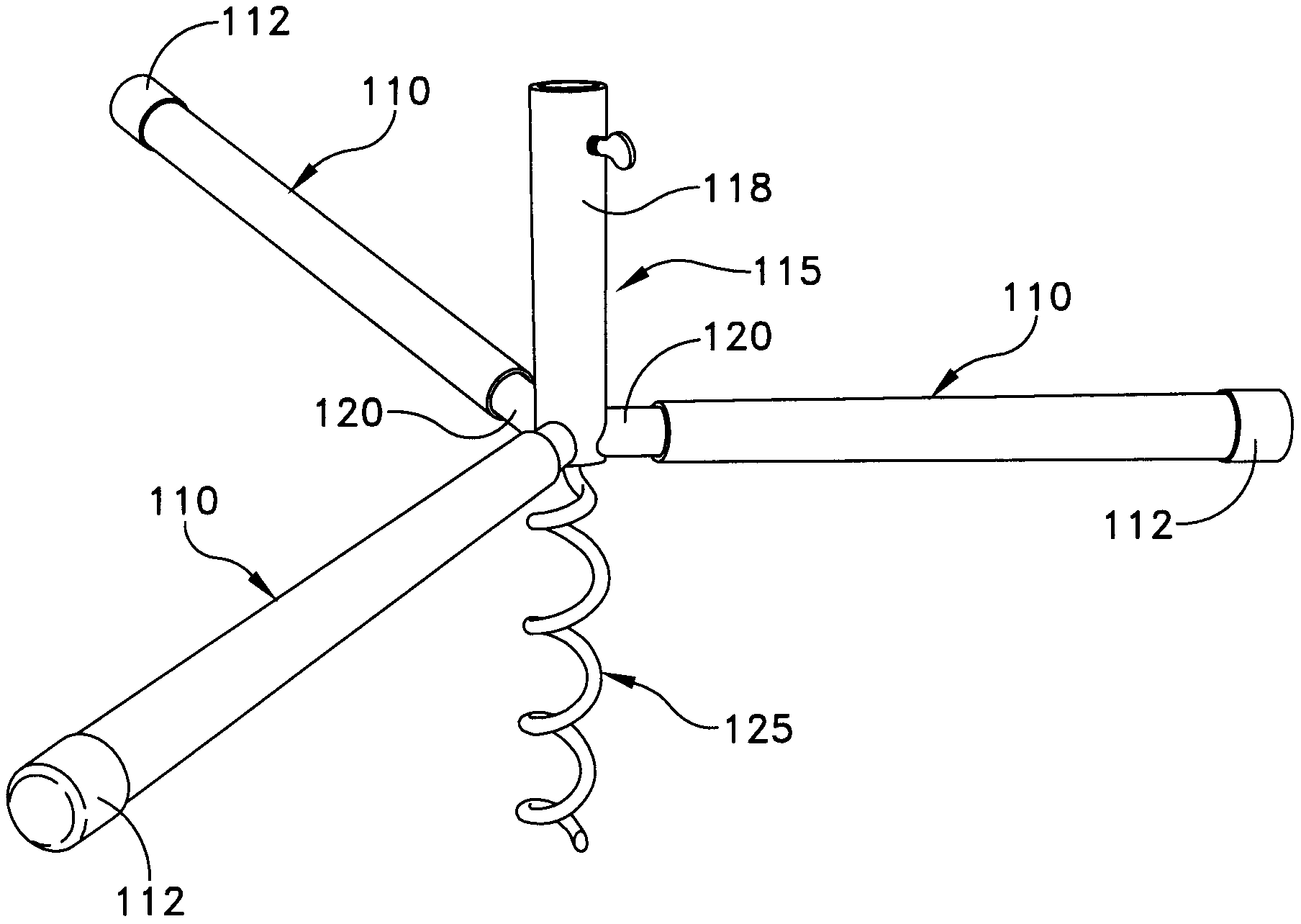
[0065]Reference is now made to FIGS. 19-22 for an illustration of the present invention. This embodiment is similar to that described in FIGS. 1-18. However, in the embodiment of FIGS. 19-22, only two port members 30 are employed. These port members are disposed in line with each other as illustrated in FIGS. 19 and 22. FIG. 20 illustrates the construction of the interconnecting member 60 that is employed with this embodiment. This interconnecting member includes only two sets of legs, namely leg sets 62A and 62B. The leg set 62A interlocks with the aperture 35 in the hood 34, as illustrated in FIG. 21. FIG. 22 illustrates the other leg set 62B engaging with the other hood 34. The other leg set 62B also includes the leg 66, similar to the leg 55 depicted in FIG. 16. This is the leg that may be depressed by the user's thumb to release the interconnecting member, enabling the separate port members to be disengaged from the housing.
third embodiment
[0066]Reference is now made to the present invention illustrated in FIGS. 23-33. In this embodiment of the present invention, the base is removable with the use of a rotatable latch member associated with the base. FIG. 23 illustrates the bottom end of the feed container 70. The top of the container may be the same as depicted previously such as in FIGS. 1 and 19. FIG. 23 also shows the apertures 72 for receiving the port member 74. The port member 74 is substantially the same as the port member previously described, such as illustrated in FIG. 6. The port member 74 includes a collar 75, a hood 76, perch 77, a projection 78 and stop 79. The inside end of the hood 76 may also include a passage for receiving an interconnecting member not specifically illustrated in this embodiment.
[0067]The primary difference between the embodiment in FIG. 23-33 and the first embodiment is that there is a different removable base 80. Refer to FIGS. 24-28 for further details of the base assembly 80. Th...
PUM
 Abstract
Description
Claims
Application Information
 - R&D Engineer
- R&D Manager
- IP Professional
- Industry Leading Data Capabilities
- Powerful AI technology
- Patent DNA Extraction
Browse by: Latest US Patents, China's latest patents, Technical Efficacy Thesaurus, Application Domain, Technology Topic.
© 2024 PatSnap. All rights reserved.Legal|Privacy policy|Modern Slavery Act Transparency Statement|Sitemap