
Winged header apparatus and method for a combine

a technology of a combine and a head is applied in the field of head, which can solve the problems of rigid headers that cannot maintain continuous height, single, wide, etc., and achieve the effect of optimal height and continuous heigh

Inactive Publication Date: 2008-12-04
CLAAS SELBSTFAHRENDE ERNTEMASCHINEN GMBH
View PDF28 Cites 66 Cited by
  • Summary
  • Abstract
  • Description
  • Claims
  • Application Information

AI Technical Summary

Benefits of technology

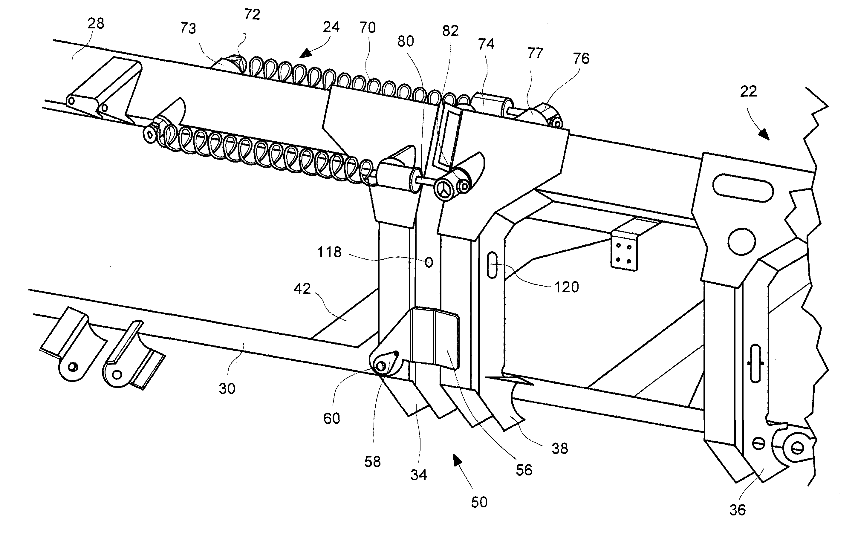
[0011]A three sectioned flexing reel is provided. Each section of the reel is mounted to a separate portion of the header. A center shaft of each reel is driven, and the center shafts of the three reels are connected with U-joints. In order to accommodate the flexing of the reel, at least one center shaft is provided on each reel with a telescoping link to the center shaft of a next reel section. In this fashion, an advantageous consistent spacing can be maintained between the lower most aspect of the reel and the header cutting system beneath it.

Problems solved by technology

The reason is that a single, wide, rigid header cannot maintain a continuous, optimal height of a cutter bar and header table that is cutting crop growing in uneven ground.

Method used


Image

  • Winged header apparatus and method for a combine
  • Winged header apparatus and method for a combine
  • Winged header apparatus and method for a combine

Examples


Embodiment Construction

[0027]The following description of the preferred embodiment(s) is merely exemplary in nature and is in no way intended to limit the invention, its application, or uses.

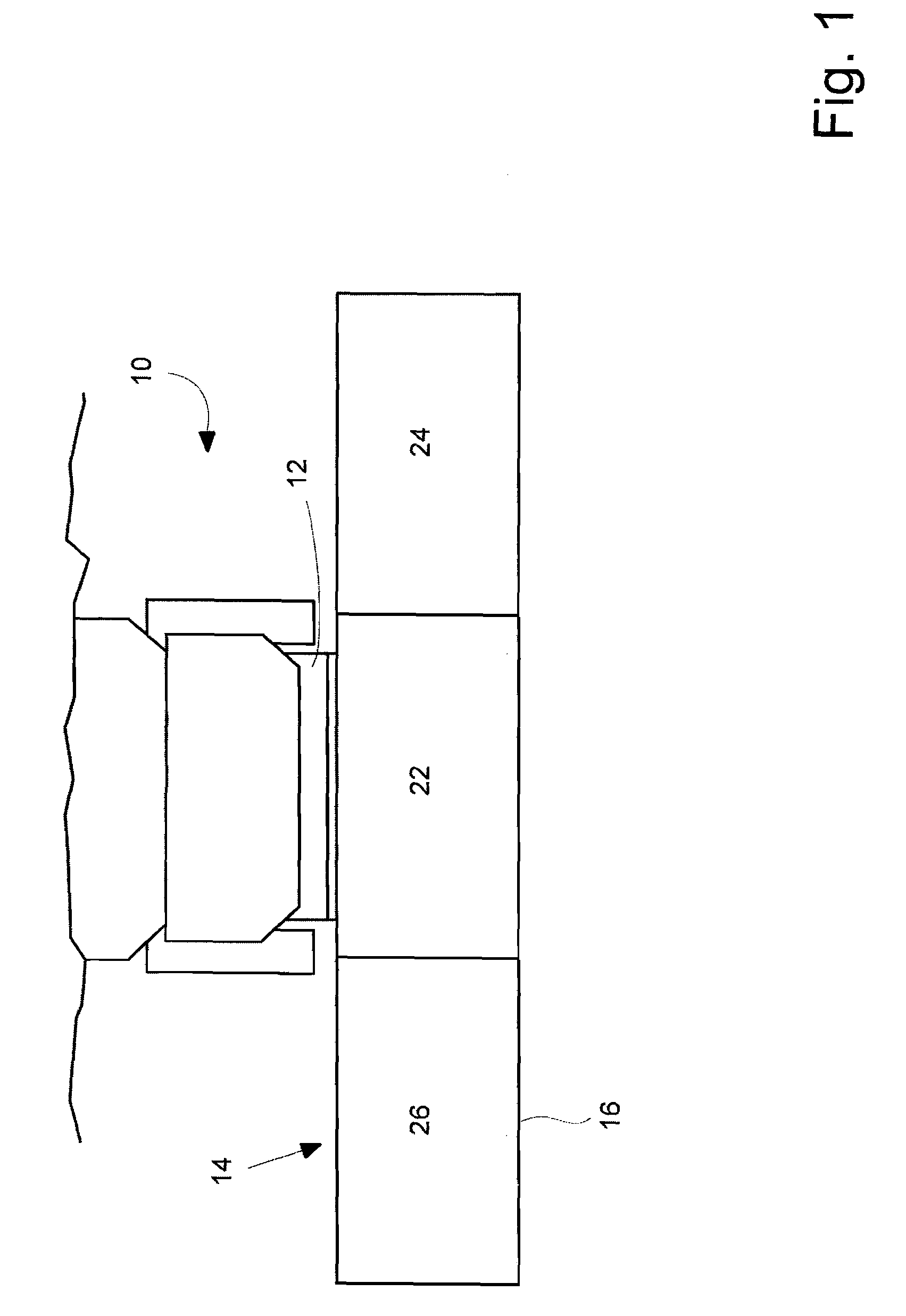
[0028]Referring now to the drawings in which like reference numbers indicate like elements, FIG. 1 is a top schematic view of a combine or harvester 10 having a feeder house 12 and a header 14. At the leading edge of the header 14 is a knife and cutter bar 16. The header receives the cut crop and transports it through the feeder house 12 into the combine where it is threshed. The depicted embodiment of the present invention is a header using conveyor belts, sometimes known to those of skill in the art as “drapers”, to convey cut crop from the laterally extended portions of the header towards the center of it and then from the center back into the feeder house 12. Lateral conveyor belt 18 transports cut crop medially to the center of the header where auger 20 propels the crop rearwards and into the feeder house.

[0029]F...


PUM


Abstract

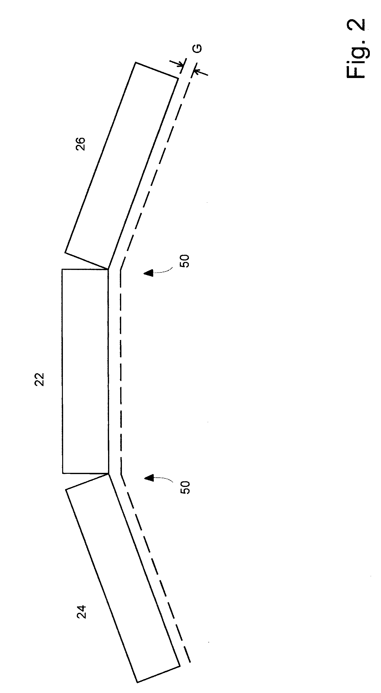
A header for a combine or a harvester comprising a center portion of said header having a feeder house position disposed to direct cut crop from the center portion to a feeder house when the header is mounted on the feeder house. At least one lateral portion of the header is attached to the center portion by a frame hinge. A draper comprised of a frame and a belt disposed to rotate over the frame extends from the lateral portion to the center portion having a draper hinge. A cutter having a curving portion is disposed at a leading aspect of the header to cut crop. The frame hinge, draper hinge and curving portion along the same axis are parallel to a direction of travel of the combine or harvester. The lateral portion can raise and lower relative to the center portion by rotation around the axis.

Description

BACKGROUND OF THE INVENTION[0001]1. Field of the Invention[0002]The present invention is in the field of headers, particularly draper headers for combines and harvesters.[0003]2. Related Art[0004]In the harvesting of commodity crops, there is a continuous need in the art for increasing speed. Accordingly, larger combines and harvesting machines having wider headers are increasingly preferred by farmers. The advantage of cutting more crop per distance traveled by a combine with a wide header, however, is often offset if the header is harvesting crop on uneven ground. The reason is that a single, wide, rigid header cannot maintain a continuous, optimal height of a cutter bar and header table that is cutting crop growing in uneven ground. It is advantageous to maintain a consistent height at which crops are cut. If a wide, rigid header harvests across a crest or trough in the ground that is less wide than the header, there will be areas in which the crop is cut at a lower and / or higher...

Claims


Application Information

Patent Timeline
IPC IPC(8): A01D43/06A01D45/00A01D57/26A01F17/02
CPCA01D41/144Y10S56/03Y10S56/10
Inventor TIPPERY, STEVESALZ, MAURICEKASTER, CRAIGPETERSEN, JENS O.
Owner CLAAS SELBSTFAHRENDE ERNTEMASCHINEN GMBH
Learn More