Ventilation exhaust fan

a technology of exhaust fans and fans, applied in the direction of ventilation systems, heating types, lighting and heating apparatuses, etc., can solve the problems of limited size, difficult installation of fans, and condensation and related problems

Inactive Publication Date: 2008-12-25
YEUNG PETER
View PDF6 Cites 45 Cited by
  • Summary
  • Abstract
  • Description
  • Claims
  • Application Information

AI Technical Summary

Problems solved by technology

They are typically used in bathrooms, where saturated air from bath, shower and sink use can cause condensation and related problems such as mold and mildew.
The ventilation fan is typically mounted in the ceiling between the joists, and is therefore limited in size by the space between the joists and between the ceiling and the floor above it.
Even at this time of relatively easy access, the fans can be difficult to install, as the fan must be positioned on the ceiling joist in such a manner that the drywall can be installed i...

Method used


Image

  • Ventilation exhaust fan
  • Ventilation exhaust fan
  • Ventilation exhaust fan

Examples


Embodiment Construction

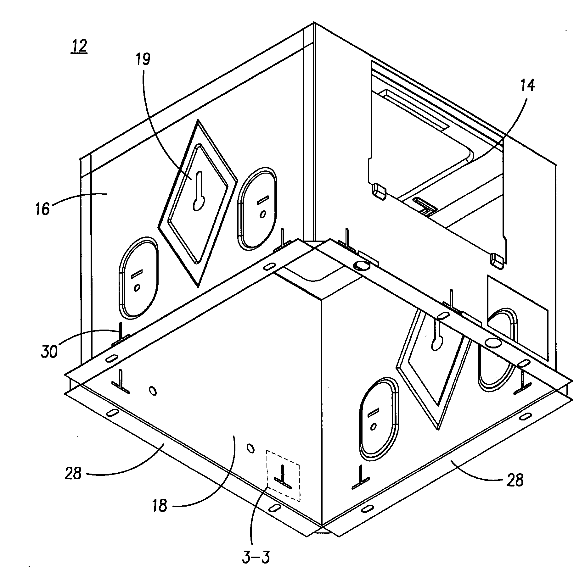
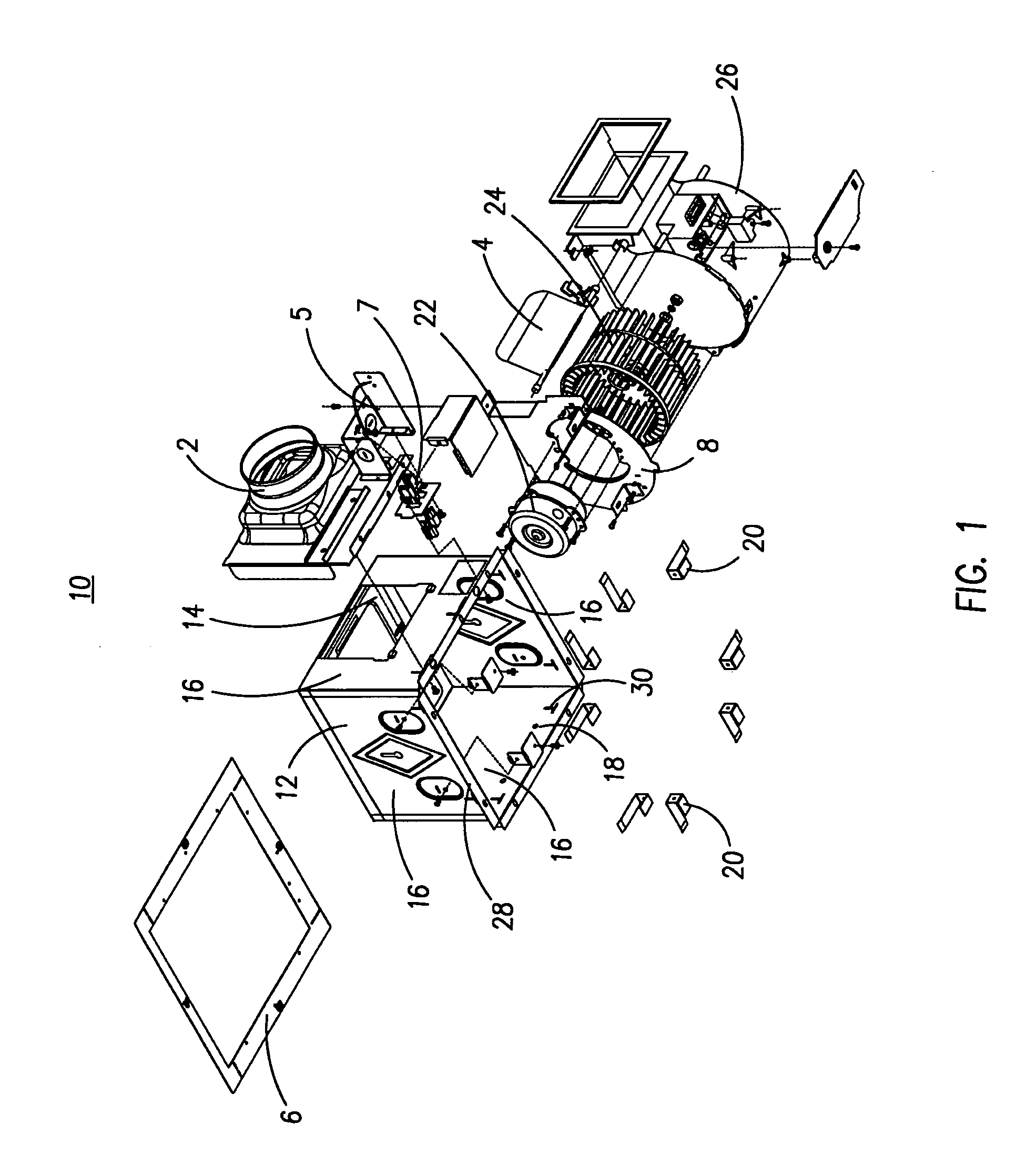
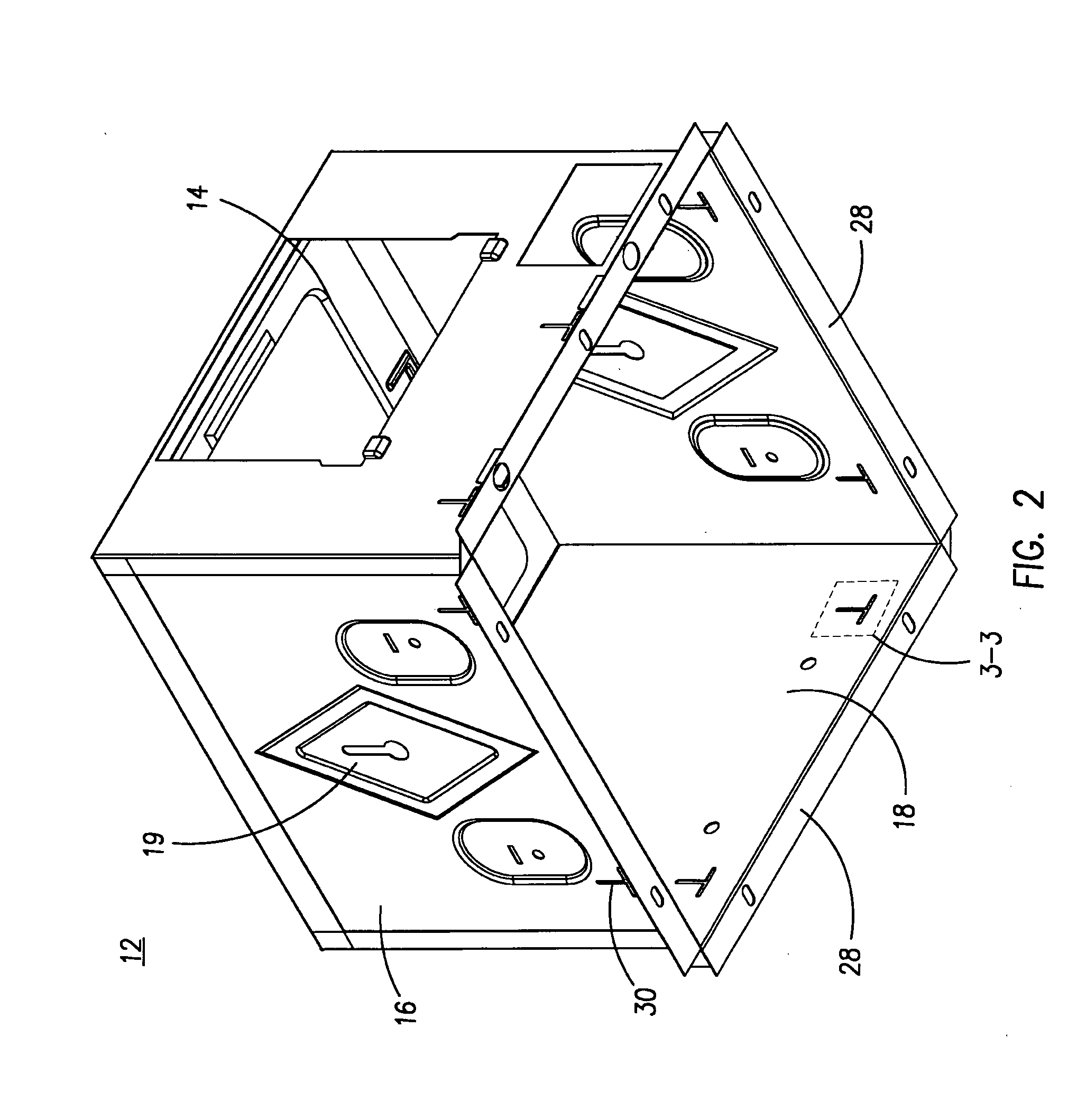
[0023]The preferred embodiment of a ventilation exhaust fan 10 is shown in FIG. 1. As shown in FIG. 1, the ventilation exhaust fan 10 has a housing 12 having a top surface 14, four sides 16 and an open bottom 18. The open bottom 18 is bordered by flanges 28 extending outwards from each of the sides, substantially perpendicular thereto. An exhaust outlet 14 is defined in one of the sides to which outlet fitting 2 is attachable. Outlet fitting 2 connects to an exhaust duct (not shown) for venting to an exterior location.

[0024]A blower housing 26 is mountable within the interior of housing 12. A motor 22 and a fan 24 are fitted within the blower housing. A cover plate 8 attachable to the blower housing has an inlet opening through which air is drawn in to the blower housing when the fan is in operation. Motor 22 is connected to the fan, and when it is activated, the motor acts to rotate the fan, thereby acting to draw air through the air inlet opening into the blower housing where it i...


PUM


Abstract

A ventilating exhaust fan has a housing having a top, four sides, and an open bottom forming an air inlet. An exhaust outlet is located in one of the sides. A motor is housed within the housing and a fan is connected to the motor. The exhaust fan is mountable within an opening in a surface. The sides of the housing have a plurality of slots through which restraints can be inserted in order to connect the housing to the surface.

Description

FIELD OF THE INVENTION[0001]The present invention relates to the field of ventilation exhaust fans for use in removing air from a bathroom or other area and venting it to an exterior location.BACKGROUND OF THE INVENTION[0002]Ventilation exhaust fans are used to vent air from a given room to an exterior location. They are typically used in bathrooms, where saturated air from bath, shower and sink use can cause condensation and related problems such as mold and mildew. By venting this saturated air, the ventilation exhaust fan can limit the amount of condensation formed. These ventilation fans are also useful in removing stale air and odors that may be present in the bathroom.[0003]The ventilation fan is typically mounted in the ceiling between the joists, and is therefore limited in size by the space between the joists and between the ceiling and the floor above it. An air inlet in the bottom of the ventilation fan draws air from the room below into the fan. An exhaust duct is connec...

Claims


Application Information

Patent Timeline
IPC IPC(8): F24F7/00F24F7/007F04D29/60
CPCF04D29/4206F04D29/626F24F7/007F24F2007/001F24F2013/205
Inventor YEUNG, PETER
Owner YEUNG PETER
Why Eureka
Try Eureka