Power plug assembly with improved connector configuration

Inactive Publication Date: 2009-01-15
HON HAI PRECISION IND CO LTD
View PDF5 Cites 12 Cited by
  • Summary
  • Abstract
  • Description
  • Claims
  • Application Information

AI Technical Summary

Benefits of technology

[0006]Accordingly, an object of the present invention is to provide a kind of power plug assem

Problems solved by technology

Moreover, the material of the inner base member 1 will be increased obviously due to the inner pin base member 1 further

Method used


Image

  • Power plug assembly with improved connector configuration
  • Power plug assembly with improved connector configuration
  • Power plug assembly with improved connector configuration

Examples


Embodiment Construction

[0017]Reference will now be made to the drawing figures to describe the present invention in detail.

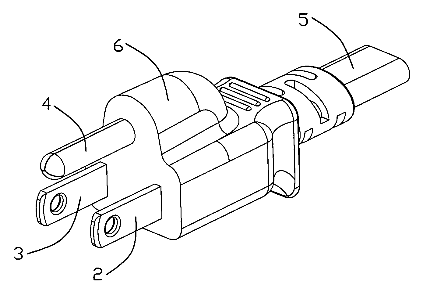
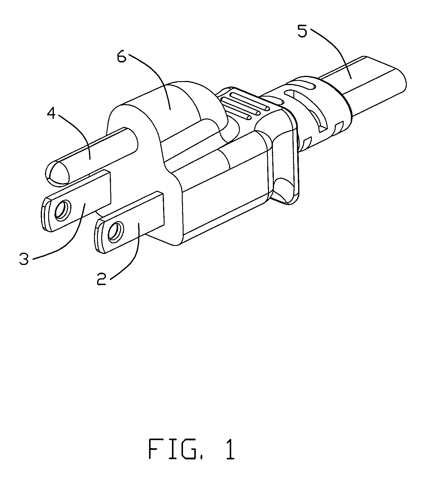
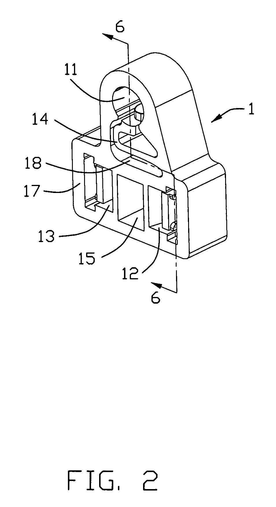
[0018]Referring to FIGS. 1 to 3, 5 and 7, a power plug assembly with improved connector configuration in accordance with the present invention adapter for mating with the complementary connector (not shown in FIGS.) includes an inner base member 1, a positive terminal 2, a negative terminal 3 and a ground terminal 4 received into the inner base portion 1, a cable 5 with a plurality of conductives 51 electrically connected to the positive, negative, ground terminals 2,3,4 and an insulative cover 6 wrapped to the inner base member 1 through injection molding.

[0019]The inner base member 1 is mainly an injection molded plasitic article and has a top portion and a bottom portion extending downwardly from the top portion. The inner base member defines a rear surface 16 and a front surface 17 opposite to the rear surface 16. The inner base member 1 has a round-section passageway 11 at its to...


PUM


Abstract

A power plug assembly with improved connector configuration, comprises an inner base member defining at least two channels each provided with a retaining member having a transition portion and a deformable positioning portion extended from thereof. At least two terminals are snugly received into the corresponding channels including a retaining portion engaged with the retaining member, a mating portion extended out of the channel and a rear portion. At least two conductive wires are electrically engaged with the rear portion of the terminals.

Description

FIELD OF THE INVENTION[0001]The present invention relates to a power plug assembly, and more particularly to a kind of power plug assembly with an improved connector configuration facilitating reliable service life and cost effective production.DESCRIPTION OF PRIOR ART[0002]Power plug assembly is more and more widely used in the connection of various home electric appliances to the AC outlet now, thus more and more manufacturers and researchers have paid more attention to design the power plug assembly which are more securely and easily to be manufactured. Generally, the power plug assembly has two-pole or three-pole electrical pin therein, and the three-pole power plug assembly is more securely in the using process, so the three-pole power plug assembly is widely used in the home electric appliances now.[0003]China Patent Issued No. CN 2153866Y discloses a kind of power plug assembly, please referring to FIGS. 1 to 5 in the above mentioned patent, the conventional three-pole power ...

Claims


Application Information

Patent Timeline
IPC IPC(8): H01R13/648
CPCH01R13/4226H01R13/504H01R2103/00H01R24/30H01R43/24H01R13/652
Inventor WANG, CHANG-YINCHENG, WEI-YALIU, SU-FENG
Owner HON HAI PRECISION IND CO LTD
Why Eureka
Try Eureka