Rotational, shear mode, piezoelectric motor integrated into a collocated, rotational, shear mode, piezoelectric micro-actuated suspension, head or head/gimbal assembly for improved tracking in disk drives and disk drive equipment

a micro-actuation and disk drive technology, applied in the field of motors, can solve the problems of insufficient collocation alone, insufficient resolution and frequency response of actuators, and limitations of vcm actuators, etc., to achieve the effect of improving data storage capacity, improving fine track positioning, and increasing track density

Active Publication Date: 2009-01-22
MAGNECOMP +1
View PDF23 Cites 27 Cited by
  • Summary
  • Abstract
  • Description
  • Claims
  • Application Information

AI Technical Summary

Benefits of technology

[0034]A rotational, shear mode, piezoelectric motor is integrated into a collocated, rotational, shear mode, piezoelectric micro-actuated suspension, head or HGA for disk drives and disk drive equipment. When used in a disk drive system with dual stage actuation, the collocated, rotational, shear mode piezoelectric micro-actuated HGA prov

Problems solved by technology

Errors in the circular shape are due to spindle run-out, vibration modes from the numerous mechanical components of the disk drive, windage, acoustic noise and many interactions thereof.
As track density increases, VCM actuators have limitations in resolution and frequency response.
These actuators suffer from insufficient frequency response at the head due to the low stiffness over the long distance between the micro-actuator and the head.
These designs suffer because they tend to distort the air-bearing surface of the slider.
However, collocation alone is insufficient to make a robust micro-actuator for disk drives.
While the micro-actuator itself may be mechanically stiff and provide high frequency response, the suspension is not mechanically stiff on the transverse axis.
Lack of stiffness reduces the fre

Method used


Image

  • Rotational, shear mode, piezoelectric motor integrated into a collocated, rotational, shear mode, piezoelectric micro-actuated suspension, head or head/gimbal assembly for improved tracking in disk drives and disk drive equipment
  • Rotational, shear mode, piezoelectric motor integrated into a collocated, rotational, shear mode, piezoelectric micro-actuated suspension, head or head/gimbal assembly for improved tracking in disk drives and disk drive equipment
  • Rotational, shear mode, piezoelectric motor integrated into a collocated, rotational, shear mode, piezoelectric micro-actuated suspension, head or head/gimbal assembly for improved tracking in disk drives and disk drive equipment

Examples


Embodiment Construction

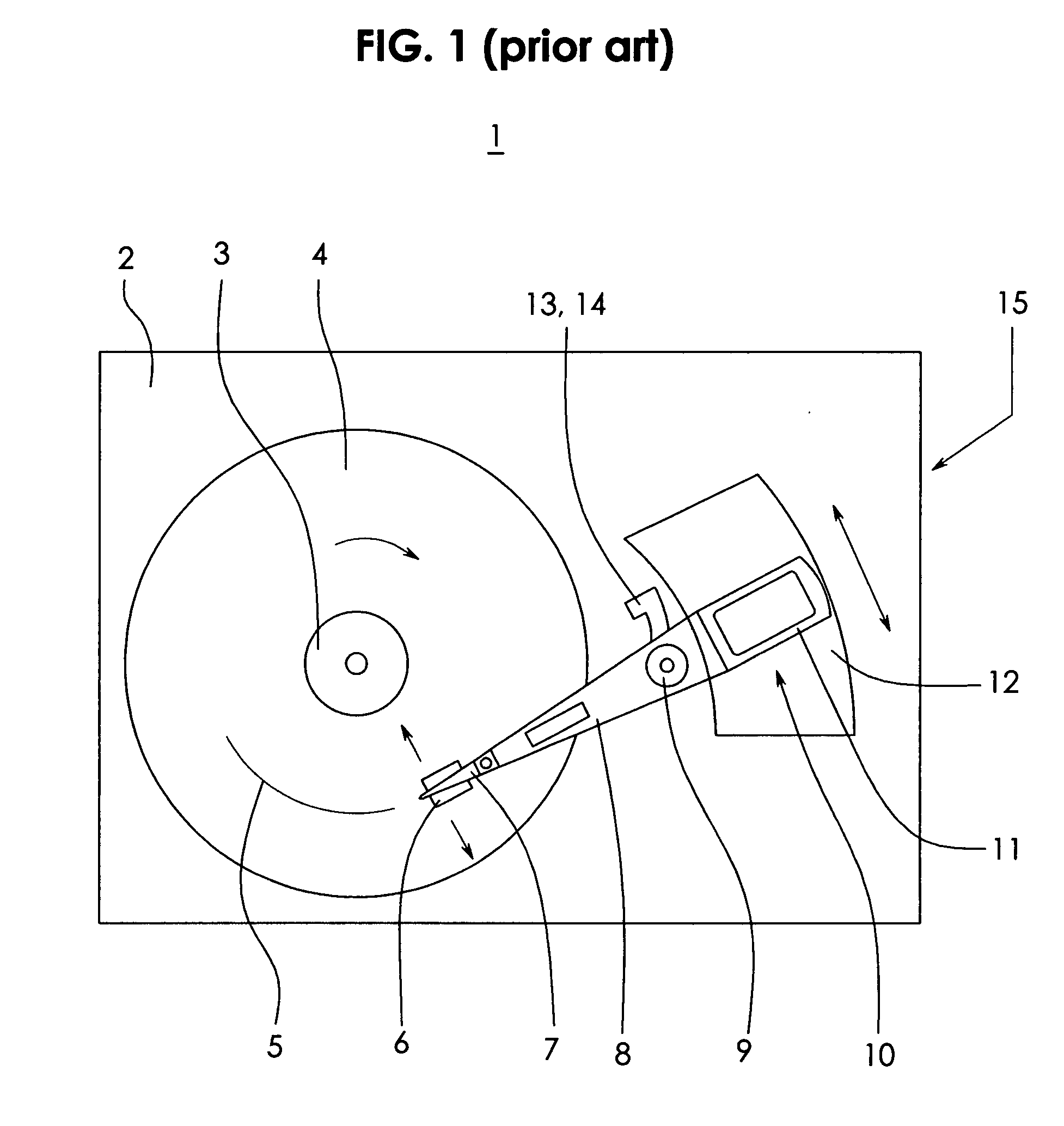
[0060]FIG. 1 illustrates a disk drive 1 that has a base 2 to which a spindle motor 3 is attached. The spindle motor 3 rotates one or more disks 4 on which concentric circles of data are recorded one track 5 at a time by recording head 6. Head 6 is attached to a flexible suspension assembly 7 that is attached to a rigid E-block 8 that rotates about a pivot bearing 9. A voice coil motor 10 comprised of a voice coil rotor 11 attached to E-block 8 and a permanent magnet stator 12 attached to base 2 responds to a control voltage 13 that conducts through a HSA flexible circuit 14 from the circuit board 15 located beneath the base 2 (not visible) to position head 6 on a desired track 5.

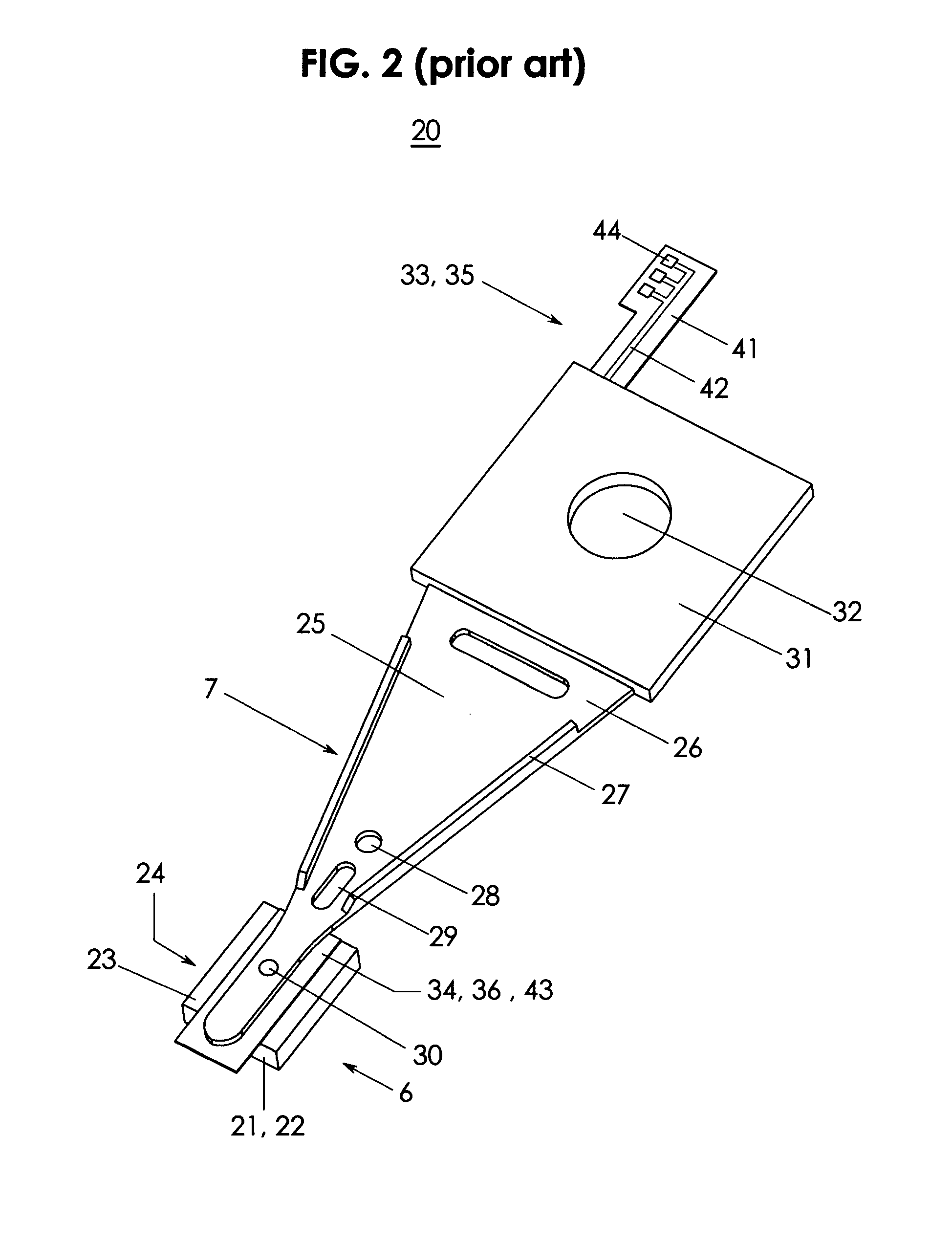
[0061]FIG. 2 illustrates a head / gimbal assembly (HGA) 20. An HGA 20 is composed of a recording head 6 and suspension assembly 7. The head 6 is comprised of a read / write element 21 with head bond pads 22 integrated on a ceramic slider 23 that has an air-bearing surface (ABS) 24. The suspension assembly 7 is c...


PUM


Abstract

A rotational, shear mode, piezoelectric motor is integrated with a suspension, head or head gimbal assembly (HGA) into a collocated, rotational, shear mode, piezoelectric micro-actuated suspension, head or head gimbal assembly (HGA) for use in disk drives and disk drive manufacturing equipment. When excited by a control voltage, the collocated, shear mode, piezoelectric micro-actuated HGA rotates the head enabling high frequency, high resolution track positioning of the read/write element. The motor is integrated with the head and flexure (collocation). The head rotates about a rotation axis that is ideally located at the center of mass of the head. A shear mode piezoelectric motor rotates the head. A collocated, rotational, shear mode, piezoelectric micro-actuated HGA has high stiffness, high frequency response, high positioning resolution, low mass and low internal vibration for improved tracking, increased track density and greater disk drive storage capacity. Furthermore, its solid integration improves shock resistance and reduces micro-contamination.

Description

FIELD OF THE INVENTION[0001]The present invention relates to a motor and more specifically to data storage technology including a read / write head, a slider, a suspension, a head gimbal assembly, a read / write head positioning mechanism, an actuator, a micro-actuator and data storage devices such as a magnetic disk drive and an optical disk drive, and finally the equipment used to manufacture and test components of said disk drives, including but not limited to, disk certifiers, disk servo writers and dynamic electrical head testers.BACKGROUND ART[0002]Increasing storage capacity is a goal in the data storage industry. Data storage products such as magnetic disk drives and optical disk drives, store digital information on rotating disks using a read / write head. The information is typically recorded in concentric, circumferential tracks about the near-center of the disk. One method to increase data storage capacity is to increase track density, where track density is defined as the num...

Claims


Application Information

Patent Timeline
IPC IPC(8): G11B21/02
CPCG11B5/4826H01L41/0993G11B5/4873G11B5/5552G11B5/483H10N30/208
Inventor SHELOR, JOHN R.
Owner MAGNECOMP
Why Eureka
Try Eureka