Intervertebral cage designs

a cage design and vertebral technology, applied in the field of spinal implants, can solve the problems of difficult to see the bone fused in mass inside the metal cage, the obscuration of the cage surface area of the end plate is not easy, and the obscuration of the cage is not easy. achieve the effect of facilitating and facilitating the access to the surface area of the end plate, without excessive obscuration

Inactive Publication Date: 2009-01-29
US SPINE INC
View PDF43 Cites 137 Cited by
  • Summary
  • Abstract
  • Description
  • Claims
  • Application Information

AI Technical Summary

Benefits of technology

[0005]This invention resides in cage systems that improve upon the prior art in various ways. In the preferred embodiments, devices are radiolucent, with markers, thereby allowing visualization of placement without excessive obscuration. Devices according to the invention eliminate multiple steps, instruments and trays, while being capable of a custom fit. The devices according to the invention permit easier and greater access to end plate surface area, and can be used with autografts, allografts, and biologics.

Problems solved by technology

However, all existing devices have certain drawbacks, including the requirement of multiple steps and tools to prepare and mold the intervertebral plates for acceptance of the devices.
Such plugs / distraction devices often get in the way of cage placement.
Existing devices also require large trays with many instruments and many cages, and it is difficult to see the bone fused in mass inside metal cages, which are radiopaque.

Method used


Image

  • Intervertebral cage designs
  • Intervertebral cage designs
  • Intervertebral cage designs

Examples


Embodiment Construction

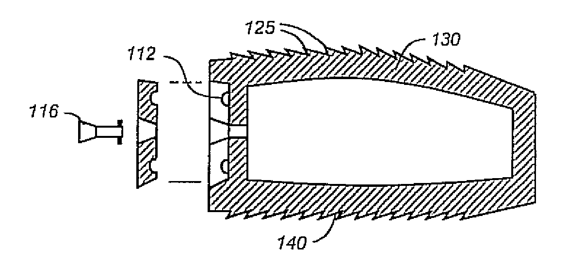
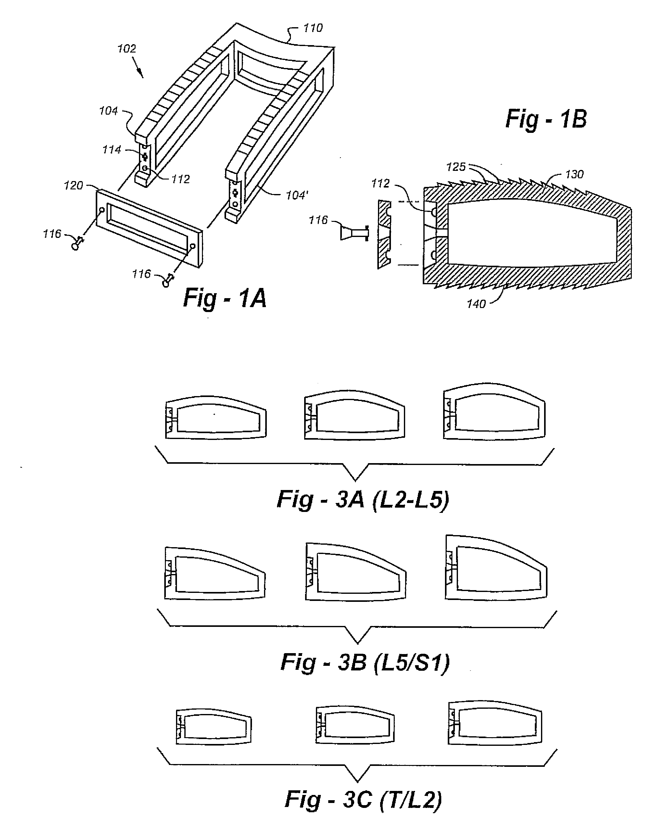
[0043]A first preferred embodiment of the invention is depicted in FIG. 1. This design includes an open-faced cage 102, which is constructed of carbon fiber or other radiolucent material but for small dot radiopaque markers (not shown). The device includes a contoured dome-shaped side walls 104, 104′ with a flat trapezoidal undersurface. Separate cages and tools may be used for the L5-S1 levels with more pronounced trapezoidal shapes. An indented back wall 110 is used to prevent neurocompression. The side walls preferably include a recessed face with nippled intents 112 and screw holes 114 to receive a locking screw 116. A closing face gate 120 is provided with non-slip nipples and locking screw holes as well.

[0044]In addition to the dome-shaped contours of the upper end plate, different shapes for the L5-S1 levels, and the indented back wall, the use of an open-face plate with gate and locking screw mechanism allows the device to be packed and closed in-situ, thereby effectively as...


PUM


Abstract

Cage systems that improve upon the prior art in various ways. In the preferred embodiments, devices are radiolucent, with markers, thereby allowing visualization of placement without excessive obscuration. Devices according to the invention eliminate multiple steps, instruments and trays, while being capable of a custom fit. The devices according to the invention permit easier and greater access to end plate surface area, and can be used with autografts, allografts, and biologics.

Description

REFERENCE TO RELATED APPLICATION[0001]This application is a continuation of U.S. patent application Ser. No. 10 / 691,854, filed Oct. 23, 2003, which claims priority from U.S. Provisional Patent Application Ser. No. 60 / 420,616, filed Oct. 23, 2002, the entire content of both of which are incorporated herein by reference.FIELD OF THE INVENTION[0002]This invention relates generally to spinal implants and, in particular, to improved intervertebral cage designs.BACKGROUND OF THE INVENTION[0003]There are many intervertebral implants to assist with stabilization and fixation, including pre-assembled mesh rings of varying size; cylindrical threaded cages; carbon fiber boxes; and bone dowels, rings, and wedges. However, all existing devices have certain drawbacks, including the requirement of multiple steps and tools to prepare and mold the intervertebral plates for acceptance of the devices.[0004]Existing implants also exhibit the need to remove / move a distraction device such as a spreader o...

Claims


Application Information

Patent Timeline
Patent Type & Authority Applications(United States)
IPC IPC(8): A61F2/44A61B17/00A61B17/02A61B17/16A61B17/17A61B17/86A61B17/88A61B19/00A61F2/00A61F2/02A61F2/28A61F2/30A61F2/46
CPCA61B17/00234A61F2250/0098A61B17/1671A61B17/1735A61B17/1757A61B17/86A61B17/8875A61B2017/00464A61B2017/0256A61B2019/444A61F2/30744A61F2/30965A61F2/447A61F2/4611A61F2002/2835A61F2002/3008A61F2002/30433A61F2002/30471A61F2002/30507A61F2002/30556A61F2002/30579A61F2002/30616A61F2002/30713A61F2002/30904A61F2002/4475A61F2002/4602A61F2002/4624A61F2002/4627A61F2002/4629A61F2002/4635A61F2220/0025A61F2220/0041A61F2220/0091A61F2250/0009A61F2250/0087A61B17/1659A61B90/92A61F2002/3071A61F2/4603A61F2/4601A61F2002/30593
Inventor FALAHEE, MARK H.
Owner US SPINE INC
Why Eureka
Try Eureka