
Surface texture measuring instrument
- Summary
- Abstract
- Description
- Claims
- Application Information
AI Technical Summary
Benefits of technology
Problems solved by technology
Method used
Image

Examples
first embodiment
[0129]A surface texture measuring instrument according to a first embodiment of the invention will be described below.
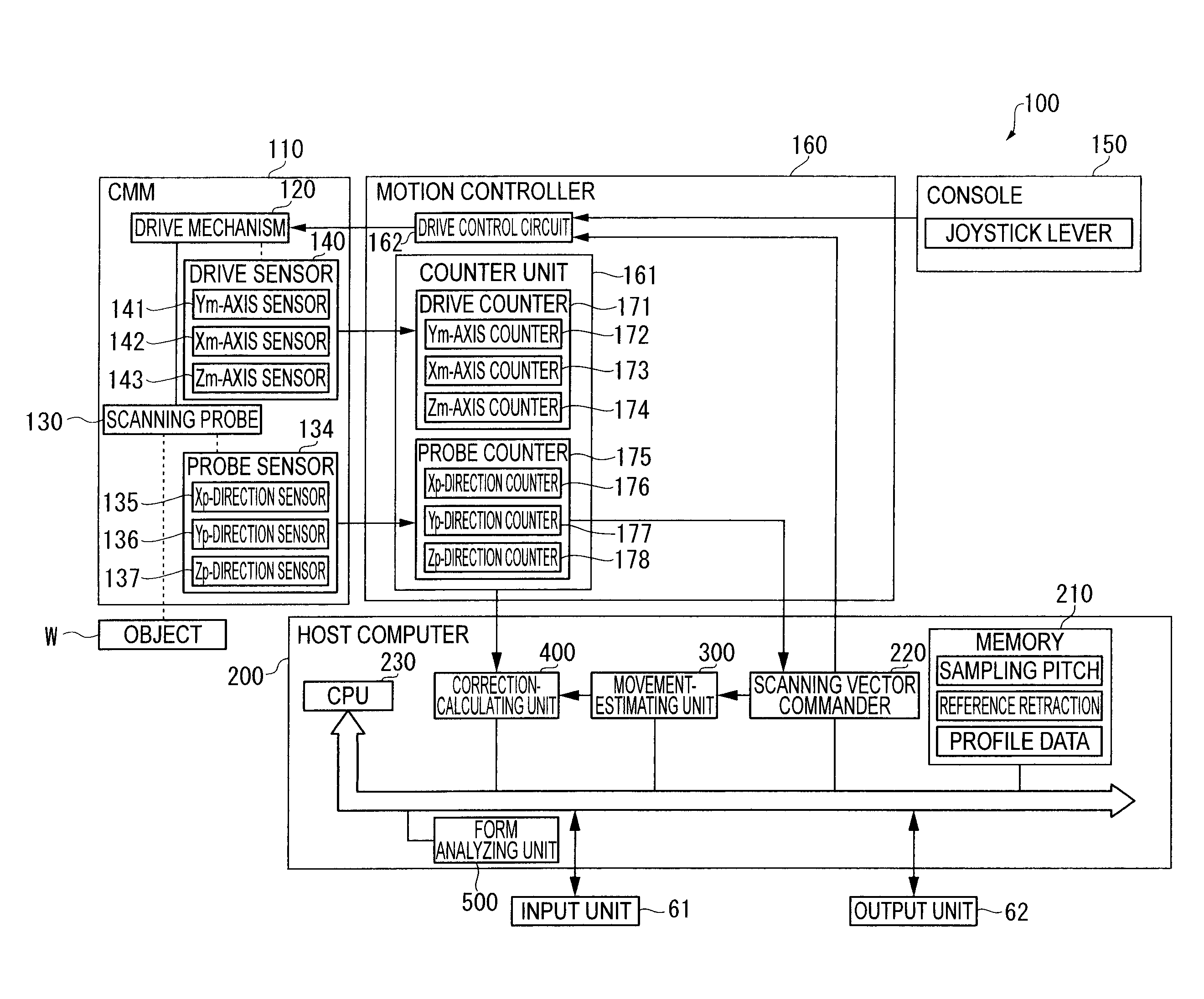
[0130]FIG. 20 shows a surface scanning measuring instrument according to the first embodiment in the form of a measuring system 100 that utilizes a scanning probe 130.
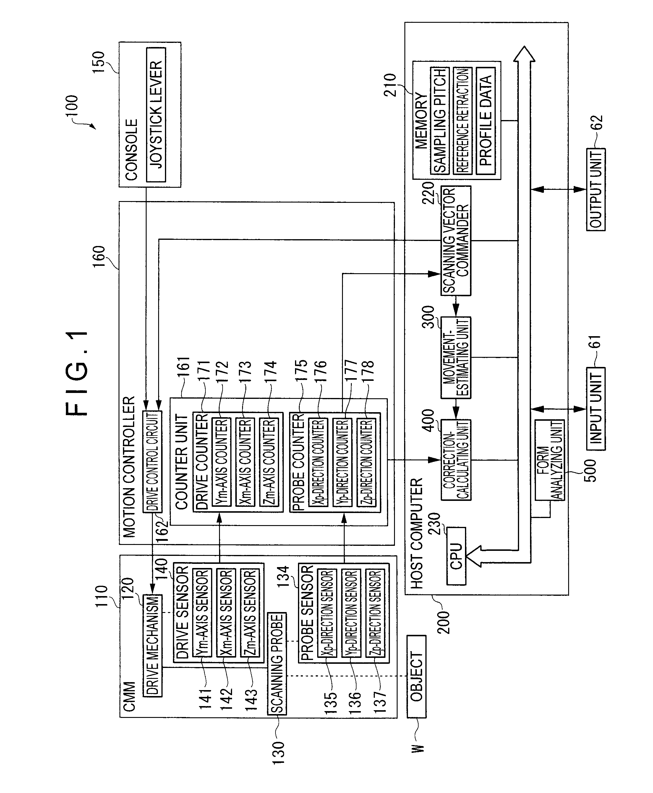
[0131]FIG. 1 shows a functional block diagram showing the measuring system 100.
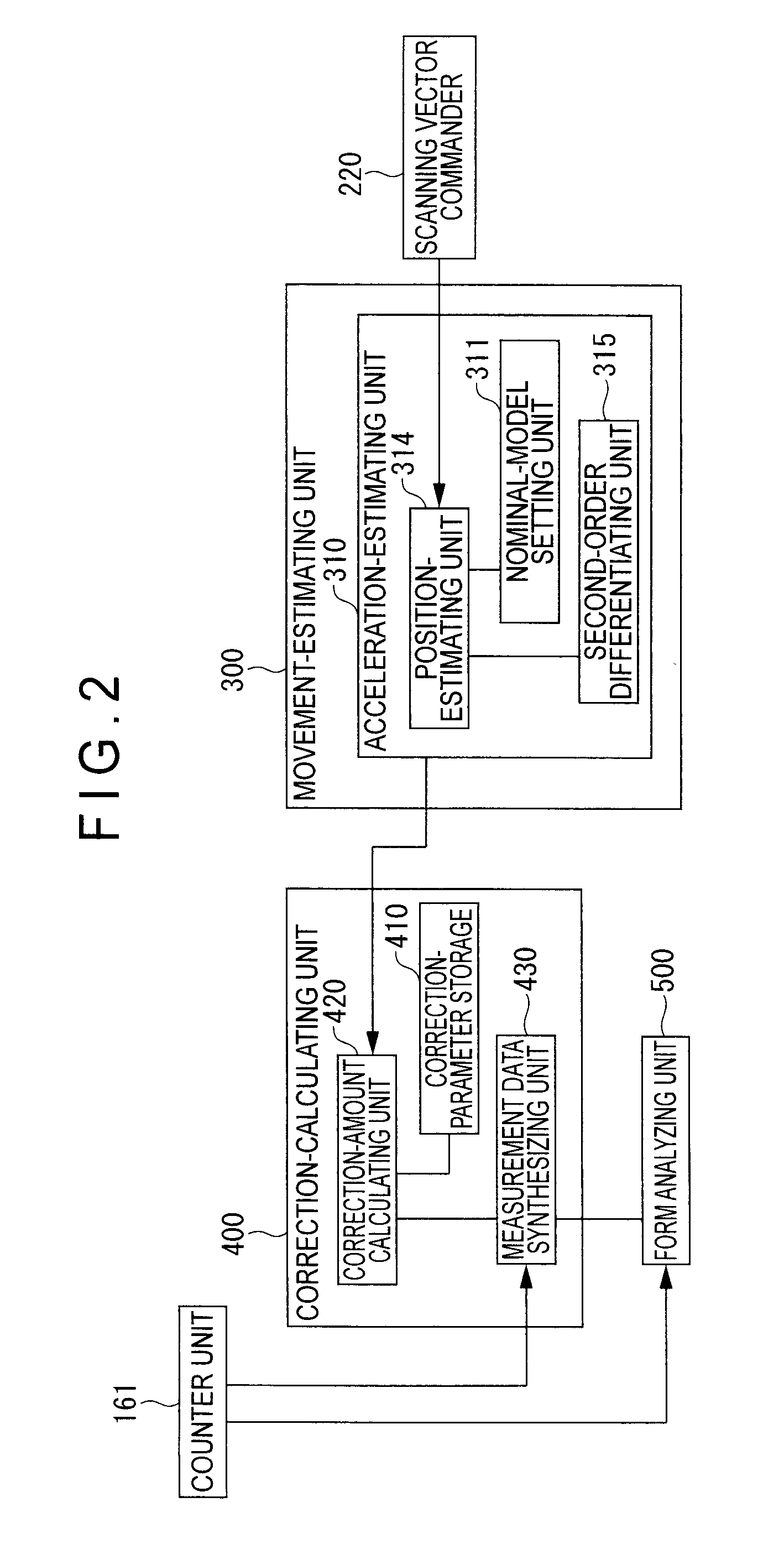
[0132]The measuring system 100 is constructed in the same manner as what has been described in the Background section, which includes a CMM 110, a console 150 for manually controlling the operation of the CMM 110, a motion controller 160 for executing drive control of the CMM 110, a host computer 200 that sends a predetermined command to the motion controller 160 and conducts calculation processing such as profile analysis of an object W, an input unit 61 through which a measurement condition and the like are input, and an output unit 62 that outputs a measurement result.
[0133]The CMM 110 includes (see FIG. 20): a table 111; ...
second embodiment
[0209]Next, a surface scanning measuring instrument according to a second embodiment of the invention will be described below.
[0210]The basic arrangement of the second embodiment is the same as the first embodiment except that the deformation caused on account of centrifugal force during the rotary movement is corrected in the second embodiment.
[0211]FIG. 4 shows a movement-estimating unit 600 and a correction-calculating unit 700 according to the second embodiment.
[0212]The movement-estimating unit 600 includes the acceleration estimating unit 310 and a frequency-estimating unit 610.
[0213]The frequency-estimating unit 610 estimates the rotary frequency of the rotary movement of the scanning probe 130.
[0214]The acceleration A is calculated by the second-order differentiating unit 315. The acceleration A(ax, ay, az) calculated by the second-order differentiating unit 315 is input into the frequency-estimating unit 610.
[0215]When a rotation radius of the rotary scanning measurement ac...
third embodiment
[0332]Next, a third embodiment of the invention will be described below.
[0333]The basic arrangement of the third embodiment is the same as that of the second embodiment. The distinctive feature of the third embodiment is the provision of an estimation-judging unit 800 for judging the accuracy of the acceleration estimation by comparing the acceleration estimated value calculated by the movement-estimating unit 600 with actual acceleration is provided.
[0334]FIG. 19 is a block diagram showing an arrangement of the movement-estimating unit 600, the correction-calculating unit 700 and the estimation-judging unit 800 according to the third embodiment.
[0335]The estimation-judging unit 800 includes: an actual-acceleration calculating unit 810 for calculating the actual acceleration based on measurement value of the coordinates detected by the counter unit 161; a difference-calculating unit 820 for calculating the difference between the estimated acceleration calculated by the movement-esti...
PUM
 Abstract
Description
Claims
Application Information