
High speed dynamic comparative latch

a dynamic comparative latch and high-speed technology, applied in the field of comparative latches, to avoid the occurrence of erroneous latch outpu

Active Publication Date: 2012-05-31
IPGOAL MICROELECTRONICS (SICHUAN) CO LTD
View PDF5 Cites 3 Cited by
  • Summary
  • Abstract
  • Description
  • Claims
  • Application Information

AI Technical Summary

Benefits of technology

The present invention provides a high-speed comparative latch that overcomes shortcomings of current technology. It only requires one clock signal and ensures that the outputted data of the latch is always effective in a whole clock cycle, avoiding erroneous output. The latch includes a pre-amplifier unit, a regenerating latch unit, and a latch unit. The pre-amplifier unit amplifies input differential signals and the regenerating latch unit uses a positive feedback to latch and retain the output of the pre-amplifier unit. The latch unit outputs the effective outputted value of the regenerating latch unit when it is in a retaining state. The new circuit design of the regenerating latch unit allows for a more efficient and reliable data transmission.

Problems solved by technology

As the clock rate of high speed systems is increasing, the requirement of precise matching of the differential clocks challenges the design and the implementation of the physical layer;2) The circuit characteristics of the regenerating latch unit B determine that during the high level of a clock cycle it is in a working status, and during the low level it is in a reset status; namely, the output of the regenerating latch unit B is effective only during the period of the high level of the clock cycle, and the output during the period of the low level of the clock cycle is ineffective;3) The regenerating latch circuit B needs a certain time to achieve latching, when it switches from a resetting status to a latching and outputting status; but the time depends on the transistors and parasitic parameters of the circuit; therefore it gets rise to an uncertain delay time of the output of the regenerating latch unit B under different technology and temperatures, relative to the rising edge of the clock, and accordingly compresses the effective values of the latch; if applied to take samples of a high speed clock, it will cause the erroneous output of the latch.

Method used


Image

  • High speed dynamic comparative latch
  • High speed dynamic comparative latch
  • High speed dynamic comparative latch

Examples


Embodiment Construction

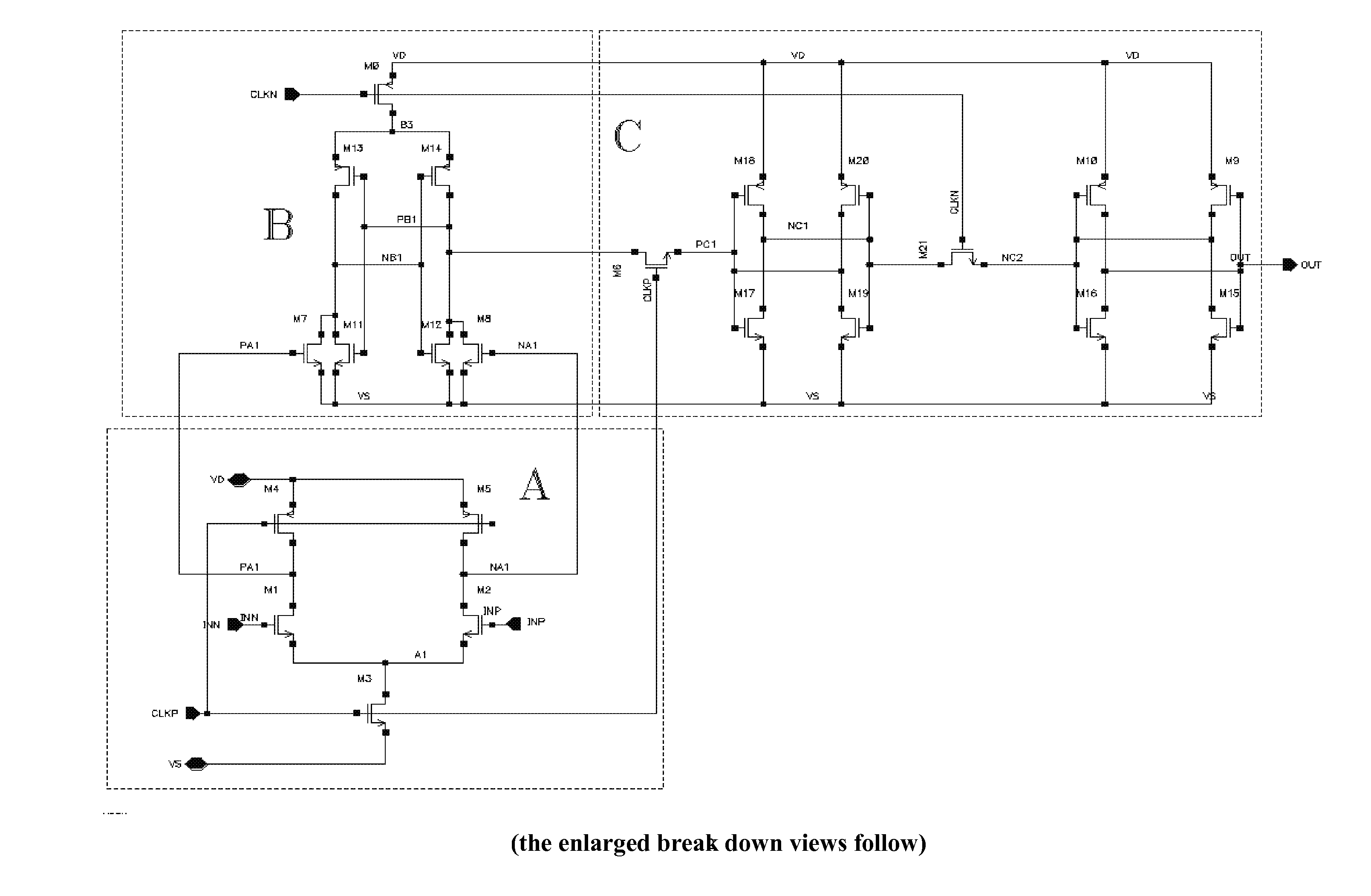
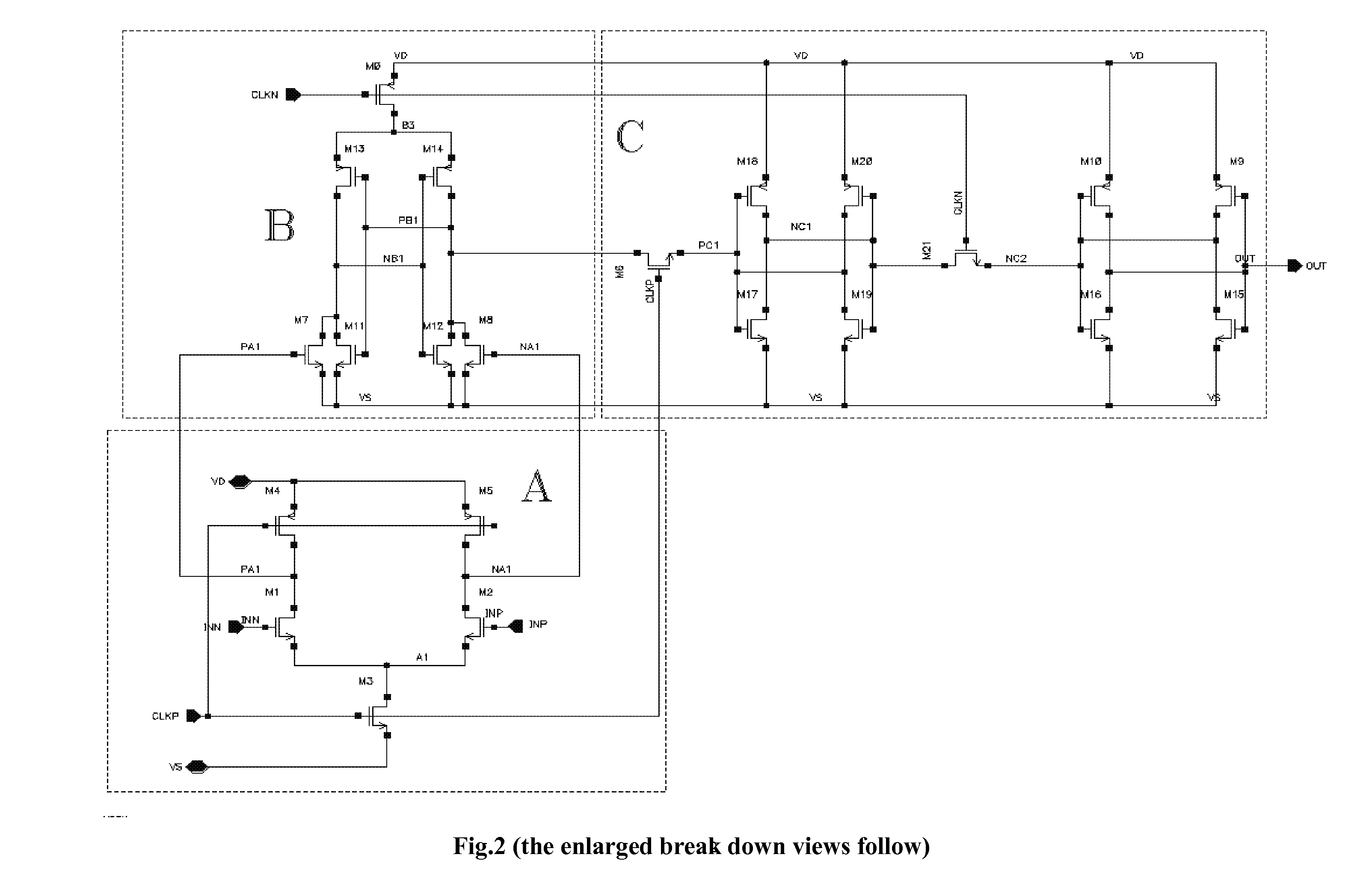
[0032]Referring to FIG. 4, INP and INN is a pair of differential signals. CLK is an input clock signal. OUT is the output of the high-speed comparative latch.

[0033]In the preferred embodiment of the present invention, the pre-amplifier unit A is consisting of a pair of input FET (Field Effect Transistor), M1 and M2, a pair of clock-controlled reset FET, M4 and M5, and a clock-controlled tail current FET M3, wherein the gate of the FET M1 is connected with the input signal INN, the drain is connected through a node PA1 to the drain of one clock-controlled reset FET M4, and the source is connected through a node A1 to the drain of the clock-controlled FET M3; the gate of the other FET M2 is connected with the input signal INP, the drain is connected in series through the node NA1 to the drain of the clock-controlled reset FET M5, and the source is connected through the node A1 to the drain of the clock-controlled FET M3; the gate of the clock-controlled FET M3 is connected to the cloc...


PUM


Abstract

A dynamic high-speed comparative latch comprises a pre-amplifier unit for enlarging input differential signals, a regenerating latch unit for latching outputted differential signals from the pre-amplifier unit by using a positive feedback, specifically, converting the output of the pre-amplifier unit into a latched result at a first state of a clock cycle, and then retaining the latched result and simultaneously resetting relevant nodes at a second state opposite to the first state of the clock cycle, and a latch unit for outputting the effective outputted value of the regenerating latch unit when the regenerating latch unit being in a retaining state. The pre-amplifier unit is connected with the regenerating latch unit, and the regenerating latch unit is connected with the latch unit. The pre-amplifier unit comprises only one input clock signal. The present invention has a simple structure, and ensures the correctness of the output result of the latch.

Description

BACKGROUND[0001]1. Field of Invention[0002]The present invention is related to a comparative latch, specifically, to a high-speed and low-offset dynamic comparative latch with less likely occurrence of mistuning.[0003]2. Description of Related Arts[0004]The high-speed dynamic comparative latch has the characteristics of high speed, low power consumption, high input impedance and full-swing output, and thus is applied widespreadly to the high-speed analog-to-digital converters, sense amplifiers and data receivers. The comparative latch is consisting of three parts, as shown in FIG. 1. One is the pre-amplifier unit, which enlarges the differential mode of input signals and outputs to the next part, regenerative latch; the second is the regenerative latch unit connected with the pre-amplifier unit, which uses a positive feedback to latch the differential mode signals; then the final part, a DFF unit (digital flip-flop) connected with the regenerative latch unit, which converts the latc...

Claims


Application Information

Patent Timeline
Patent Type & Authority Applications(United States)
IPC IPC(8): H03K3/023
CPCH03K5/249H03K3/356173
Inventor LI, BINWU, GUOSHENG
Owner IPGOAL MICROELECTRONICS (SICHUAN) CO LTD
Learn More