
Improved image acquisition

a technology of image acquisition and detection device, applied in tomography, x/gamma/cosmic radiation measurement, instruments, etc., can solve the problems of methods that do not consider distinct discontinuities and inherent errors in signal quantification, and achieve the effect of improving ct image acquisition methods

Active Publication Date: 2021-02-11
KONINKLJIJKE PHILIPS NV
View PDF0 Cites 0 Cited by
  • Summary
  • Abstract
  • Description
  • Claims
  • Application Information

AI Technical Summary

Benefits of technology

The patent describes a method to improve the detection and acquisition of images using electromagnetic radiation. The method includes estimating the incomplete cycle of the radiation, caused by interruptions or changes in the beam, by analyzing the cycle time before the interruption. This estimate is used to correct the output of the detection device and improve image acquisition. The method can compensate for discontinuities caused by changes in wavelength or blank periods of the radiation, and it can also modify the gain of the cycle during image acquisition to improve the spectral results. The method can be used in any readout topology and it reduces the need for frames with different integration periods based on the DFS position.

Problems solved by technology

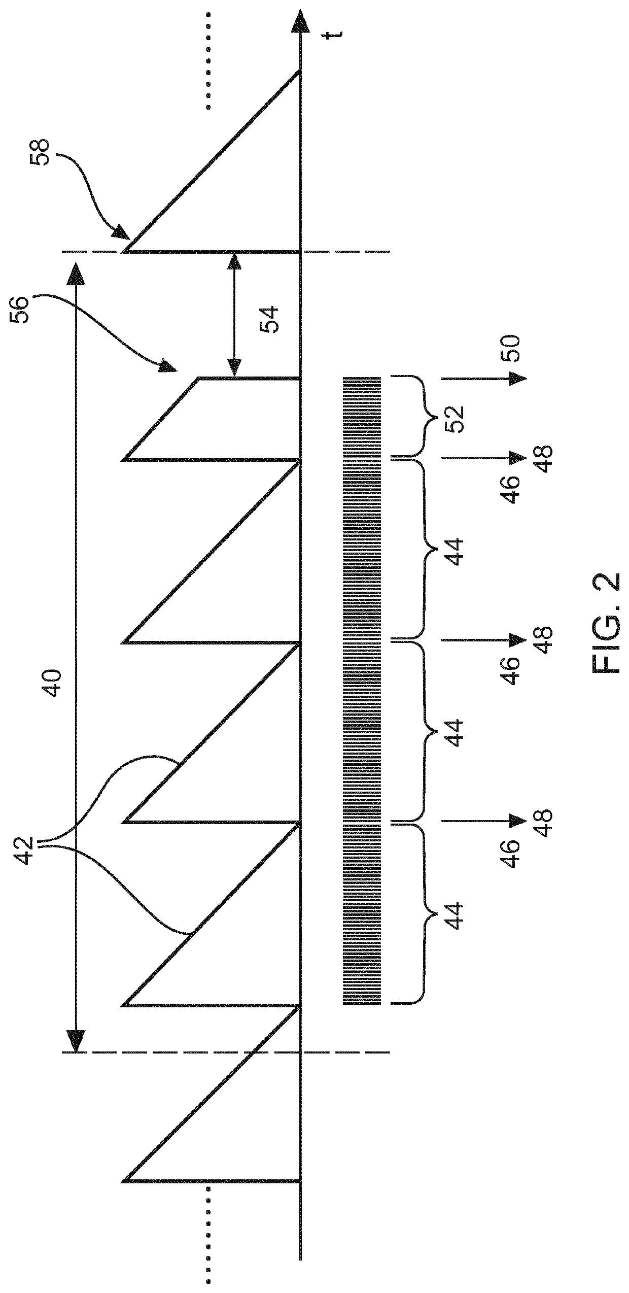
It however inherently can entail a certain amount of error in signal quantification in the event of e.g. X-ray being shut off for a short period of time.
However, these methods do not consider distinct discontinuities.

Method used


Image

  • Improved image acquisition
  • Improved image acquisition
  • Improved image acquisition

Examples


Embodiment Construction

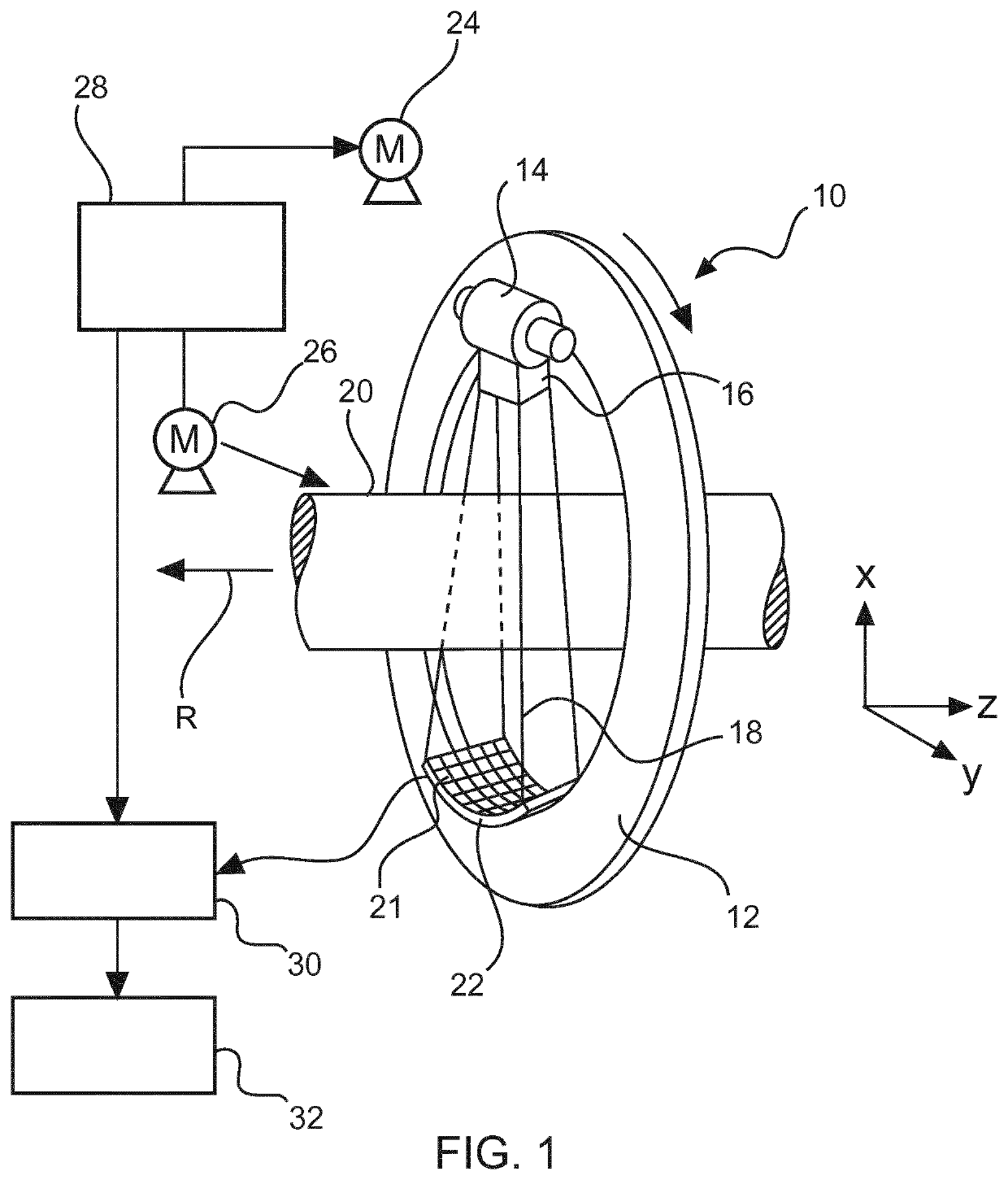
[0037]FIG. 1 shows schematically and exemplarily an imaging system10 according to the present invention for imaging an object, in this example being a computed tomography (CT) apparatus. The CT apparatus 10 includes a gantry 12, which is capable of rotation about a rotational axis R, which extends parallel to a z direction. A radiation source 14 (also called photon source), which may be a polychromatic X-ray tube, is mounted on the gantry 12. The radiation source 14 is provided with a collimator 16, which forms a (e.g. conical) radiation beam 18 from the radiation (photons) generated by the radiation source 14. The radiation traverses an object of examination, such as a patient, arranged in an (e.g. cylindrical) imaging area 20 (also called examination zone).

[0038]After having traversed the imaging area 20, the radiation beam 18 is incident on a detection device for X-rays 22 (detector for detecting ionizing radiation), which comprises a two-dimensional detection surface. The detect...


PUM


Abstract

The present invention relates to a detection device for X-rays, an imaging system and a method for detecting electro-magnetic radiation using a detection device for X-rays, wherein an estimate of an incomplete measurement is acquired prior to a discontinuity of the electromagnetic radiation, wherein the discontinuity is a change or interruption in a beam or in an intensity of the electromagnetic radiation.

Description

FIELD OF THE INVENTION[0001]The present invention relates to a detection device for X-rays, an according imaging system, a method for detecting electromagnetic radiation using the detection device for X-rays, a computer program element and a computer readable medium.BACKGROUND OF THE INVENTION[0002]The advent of new Computed Tomography (CT) image acquisition methods, e.g. Sparse sampling with Grid Switch tubes, kVp switching (kVp is a common notation for tube acceleration voltage) or grid filters, require that the readout electronics do not propagate signal information across a distinct discontinuity of the X-ray intensity which can happen either by a change of spectrum or blank period of an X-ray tube.[0003]A known readout topology is that of a CT readout ASIC comprising a current to frequency converter or ratiometric converter or folded integration converter, allowing to achieve a large dynamic range and resolution. It however inherently can entail a certain amount of error in sig...

Claims


Application Information

Patent Timeline
Patent Type & Authority Applications(United States)
IPC IPC(8): G01T1/17G01T1/29G01T1/20A61B6/00
CPCG01T1/17G01T1/2985A61B6/032A61B6/4208G01T1/20184A61B6/54A61B6/4035
Inventor STEADMAN BOOKER, ROGERPROKSA, ROLAND
Owner KONINKLJIJKE PHILIPS NV
Learn More