Information reproduction apparatus

a technology of information reproduction and optical disk, applied in the direction of data recording, optical recording heads, instruments, etc., can solve the problems of complex circuitry in the following stage, inability to capture readout signals (rf signals) from sub spots, and factor of forcing up costs, etc., to improve compatibility, data rate, reliability

Inactive Publication Date: 2006-04-20
HITACHI MEDIA ELECTORONICS CO LTD
View PDF11 Cites 15 Cited by
  • Summary
  • Abstract
  • Description
  • Claims
  • Application Information

AI Technical Summary

Benefits of technology

[0020] For optical information reproduction devices compatible with multiple wavelengths and multiple standards, employing multiple source beams with dif

Problems solved by technology

Thus, a readout signal (RF signal) cannot be captured from the sub spots.
If laser beams with three or more wavelengths from the light source are used, the sub spot detector must be divided into even more sub-planes and, accordingly, the circuitry in the following stage must become complex, which was a factor of forcing up costs.
Given that the device is intended to support information reproduction from diverse optical disks, according to a number of standards, as regards, e.g., a ROM medium (read only recording medium), there was a problem in which tracking errors cannot be detected correctly by differential phase detection, because the four-

Method used


Image

  • Information reproduction apparatus
  • Information reproduction apparatus
  • Information reproduction apparatus

Examples


first embodiment

(Optics Section Having a Separately-Located Radio-Frequency (RF) Signal Detector Plane)

[0059] A configuration example of an optical information reproduction apparatus equipped with a detector plane dedicated to RF signal detection, according to the present invention, is discussed, using FIGS. 1 through 20. First, a configuration example of a light receiving optics section of the information reproduction apparatus, according to the present invention, is presented, using FIGS. 5 and 14.

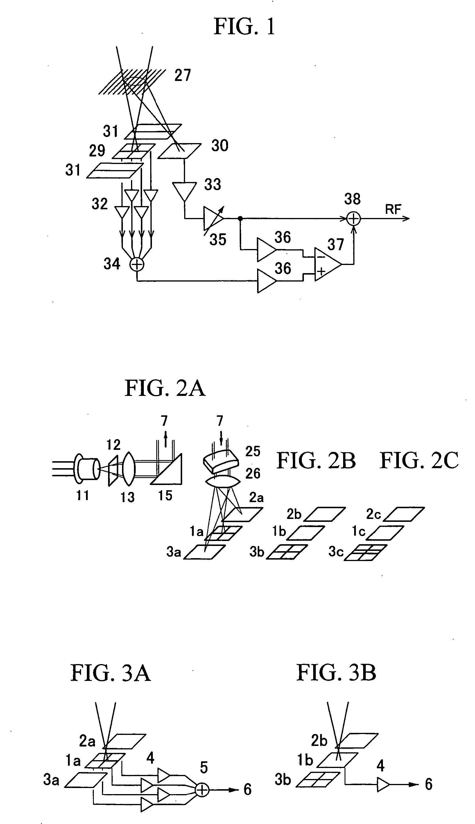
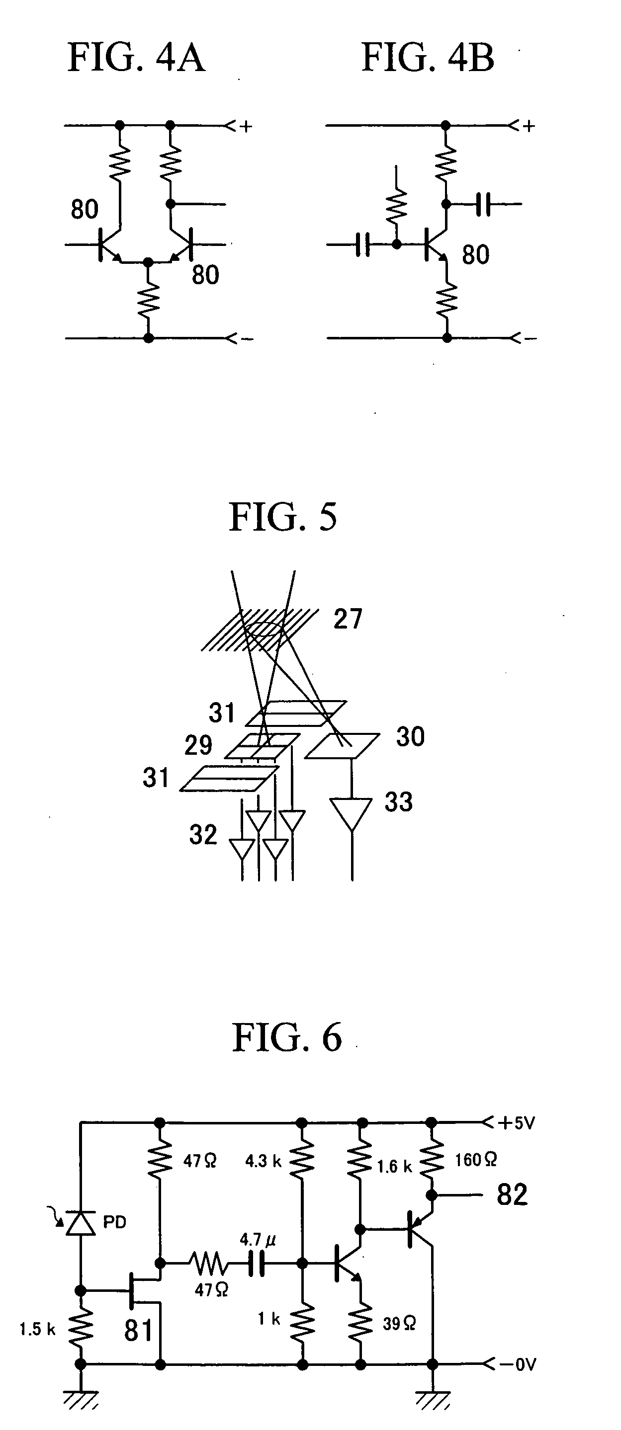
[0060]FIG. 5 shows an example of arrangement of photodetectors having detector planes and a photocurrent amplifier connected close to the main elements, according to a differential push-pull method, which is one three-spot method. A beam from a laser light source hits an information recording medium, the light amount of the beam is modulated by information recorded there, and the beam is reflected by the medium. The reflected beam, after converged through a detection lens, enters the present optics s...

second embodiment

(RF Signal Amplification with the AC Amplifier)

[0072] A configuration of the AC amplifier employed as the photocurrent amplifier according to the present invention and its effect are discussed, using FIGS. 4 through 8. As described above in the “Background” section, a differential amplifier shown in FIG. 4A is generally used as a DC amplifier to correctly amplify a change in DC for the amount of light detected, relative to a signal potential corresponding to the zero amount of light. In circumstances where amplifier noise must be constrained, the S / N ratio has been deteriorated by about 6 dB by this differential amplification.

[0073] By contrast, if the AC amplifier shown in FIG. 4B can be used, noise generated by the amplifier can be suppressed to a minimum level. The amplifier noise can be improved by above 6 dB as compared with the DC amplifier shown in FIG. 4A. Because of AC coupling, the AC amplifier cannot amplify a change in DC voltage. However, the AC amplifier does not ha...

third embodiment

(First Arrangement for Generating Combined RF Readout Signals)

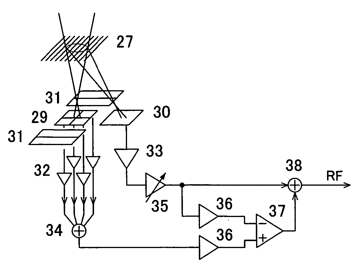
[0081] Next, a first arrangement example for generating combined RF signals with lower noise from RF signals amplified by the AC amplifier and signals amplified through DC amplifiers from the four-quadrant photodetector planes according to the present invention and its effect are discussed, using FIG. 1 and FIGS. 8 through 16.

[0082]FIG. 1 shows an optical head's photodetecting section and circuitry in the vicinity of the photodetecting section (optical head) in the optical information reproduction apparatus. A diffraction grating located in front of the photodetector chip splits an incident beam to the photodetectors into two or more beam components. The arrangement of FIG. 1 is designed to detect TR and AF signals by the three-spot method. The entire structure of the apparatus will be described later, using FIG. 20.

[0083] Among three spot beams directed to hit the photodetectors, a center spot beam is split by the di...


PUM


Abstract

For optical disk apparatus compatible with multiple standards, employing multiple source beams with different wavelengths, less costly implementations of the photodetecting optics section and associated circuitry are presented. A photodetector plane dedicated to RF signal detection is provided. By bandwidth combining an RF signal detected by this plane is with another signal from other photodetector planes, S/N ratio is improved. For beam splitting, diffraction gratings are used and adjustment precision requirement is relaxed greatly. AC amplifiers can be used as RF photocurrent amplifiers.

Description

CLAIM OF PRIORITY [0001] The present application claims priority from Japanese application JP 2004-302367 filed on Oct. 18, 2004, the content of which is hereby incorporated by reference into this application. FIELD OF THE INVENTION [0002] The present invention relates to optical disk apparatus, optical disk media, and optical information storage devices that record or reproduce information to / from a recording medium, using light. In particular, the invention relates to information reproduction apparatus compatible with multiple schemes / standards and having high-speed and high-density recording performance, using a plurality of source beams with different wavelengths and high-density disks using blue light or blue-violet light in which, especially, readback signal quality is a challenge. BACKGROUND OF THE INVENTION [0003] Optical recording media typified by optical disks are being improved to have higher information recording density and higher information reading speed. However, su...

Claims


Application Information

Patent Timeline
IPC IPC(8): G11B7/135
CPCG11B7/1275G11B7/131G11B7/1353G11B7/1381G11B2007/0006
Inventor ISSHIKI, FUMIOWATANABE, KOICHISHIMADA, KENICHIKUROKAWA, TAKAHIRO
Owner HITACHI MEDIA ELECTORONICS CO LTD
Why Eureka
Try Eureka