Method for Sending and Detecting Downlink Control Information
- Summary
- Abstract
- Description
- Claims
- Application Information
AI Technical Summary
Benefits of technology
Problems solved by technology
Method used
Image

Examples
example 1
[0078]The DCI format blindly detected by the terminal on the anchor component carrier is determined by the related configurations of the higher layer signaling (the RNTI and the transmission mode). The DCI format to be detected on the anchor component carrier includes the DCI format for common control information scheduling (namely the DCI format for bearing the uplink power control information, system message, paging, RACH Response and so on) and DCI format corresponding to the UE-specific third type DCI.
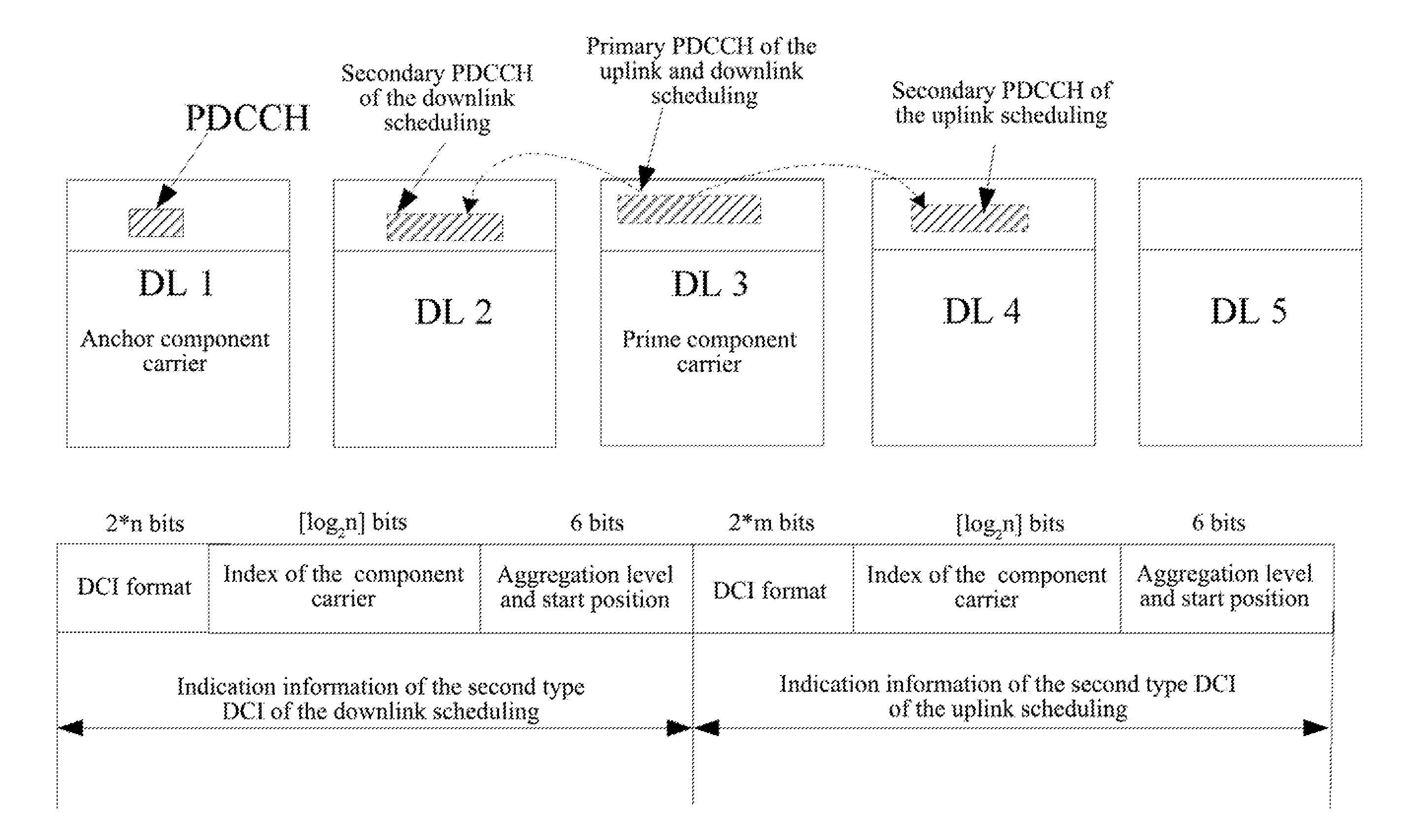
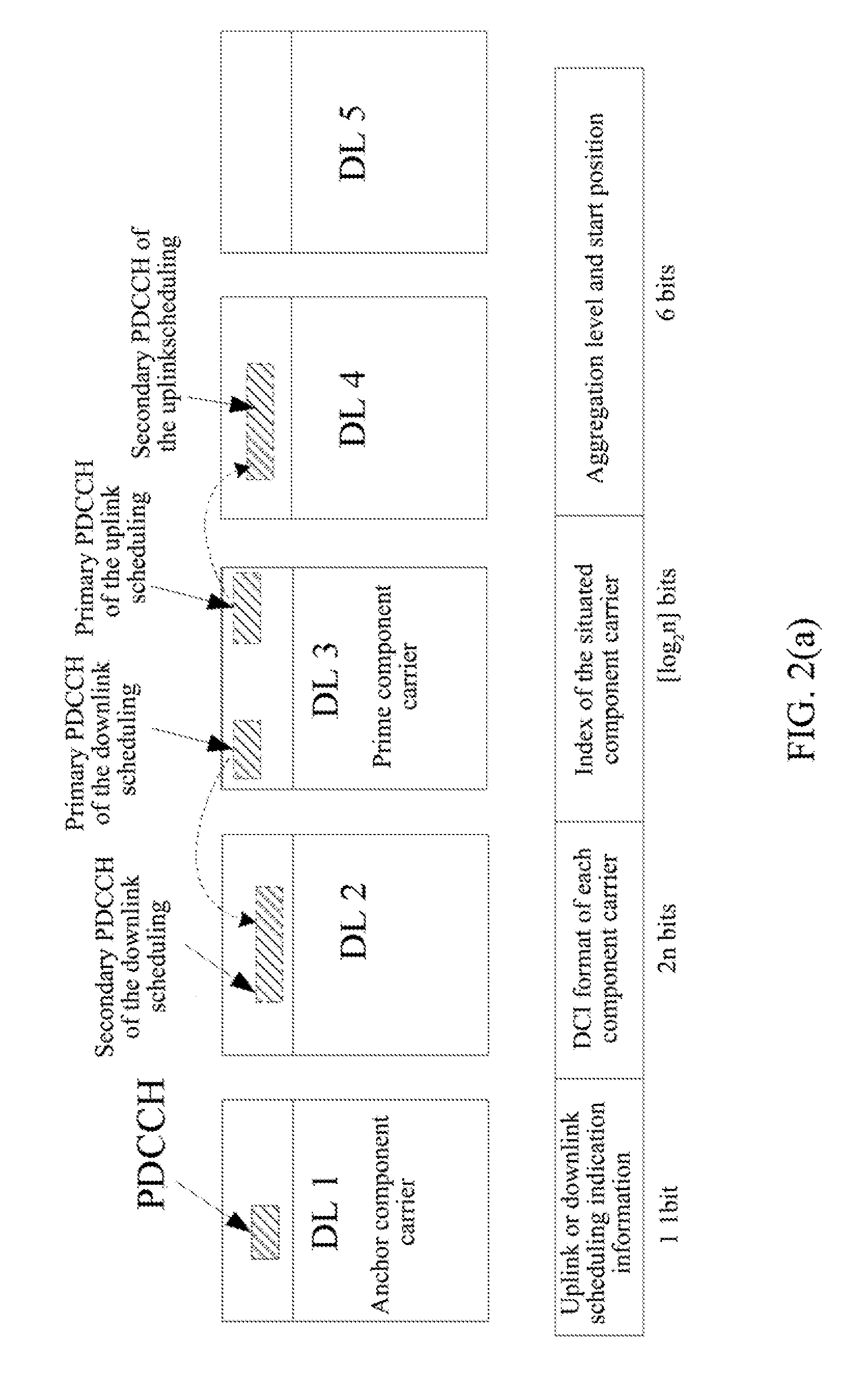
[0079]Method 1
[0080]As shown in FIG. 2 (a), the uplink scheduling and downlink scheduling use one piece of the third type DCI to indicate respectively.
[0081]The information borne in the third type DCI is: uplink scheduling information or downlink scheduling indication information, 1 bit, for indicating the uplink or downlink scheduling;
[0082]2*n bits (2 bits per component carrier, wherein 00 denotes that the corresponding component carrier does not have the DCI format, and each of ...
application example 1
[0098]The terminal receives and sends data on n (1
[0099]The DCI format blindly detected by the terminal on the anchor component carrier is determined by the related configurations (the RNTI and the transmission mode) of the higher layer signaling. The DCI format blindly detected on the prime component carrier includes the DCI format for common control information scheduling (namely the DCI format for bearing the uplink power control, system message, paging, RACH Response and so on) and DCI format corresponding to the UE-specific third type DCI.
[0100]If the terminal detects the third type DCI on the prime component carrier, then the terminal obtains the codewords of the second type DCI from the CCE set on the specific component carrier according to the borne indication information of th...
application example 2
[0101]The terminal receives and sends data on n (1
[0102]The DCI format blindly detected by the terminal on the anchor component carrier is determined by the related configurations (the RNTI and the transmission mode) of the higher layer signaling. The DCI format respectively blindly detected on the two prime component carriers includes the DCI format for common control information scheduling (namely the DCI format for bearing the uplink power control, system message, paging, RACH Response and so on) and DCI format corresponding to the UE-specific third type DCI.
[0103]If the terminal detects the third type DCI on the prime component carrier, then the terminal obtains the codewords of the second type DCI from the CCE set on the specific component carrier according to the borne indic...
PUM
 Abstract
Description
Claims
Application Information