Stator arrangement

Inactive Publication Date: 2018-11-22
ROLLS ROYCE PLC
View PDF4 Cites 2 Cited by
  • Summary
  • Abstract
  • Description
  • Claims
  • Application Information

AI Technical Summary

Benefits of technology

[0010]A pressure profile of the second aerofoil, when in the second position, may be substantially identical to that of the first aerofoil. Thus, the arrangement may be optimised for either or both of tone noise levels by providing a relatively higher number of aerofoils generating a substantially equivalent frequency or tone; and broadband noise levels by providing a relatively lower number of aerofoils. Thus, the arrangement provides a first configuration in a first position configured for broadband

Problems solved by technology

During operation of a gas turbine engine, it is common for an amount of noise to be produced.
Gas turbine engines are commonly affected by tone noise and broadband noise.
Conversely, broadband noise has an unsteady and chaotic character, mainly

Method used


Image

  • Stator arrangement
  • Stator arrangement
  • Stator arrangement

Examples


Embodiment Construction

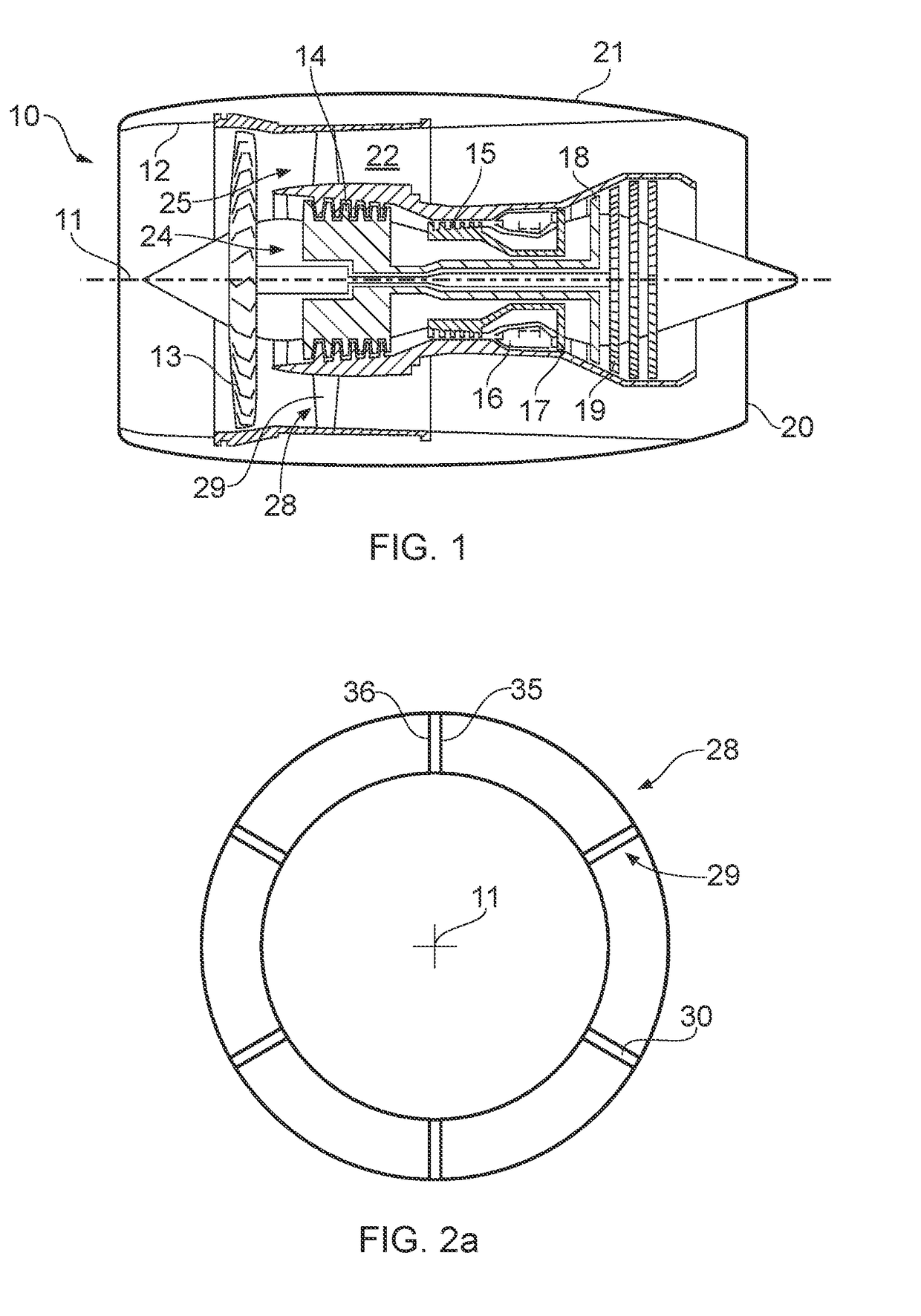
[0044]With reference to FIG. 1, a gas turbine engine is generally indicated at 10, having a principal and rotational axis 11. The engine 10 comprises, in axial flow series, an air intake 12, a propulsive fan 13, an intermediate pressure compressor 14, a high-pressure compressor 15, combustion equipment 16, a high-pressure turbine 17, an intermediate pressure turbine 18, a low-pressure turbine 19 and an exhaust nozzle 20. A nacelle 21 generally surrounds the engine 10 and defines both the intake 12 and the exhaust nozzle 20.

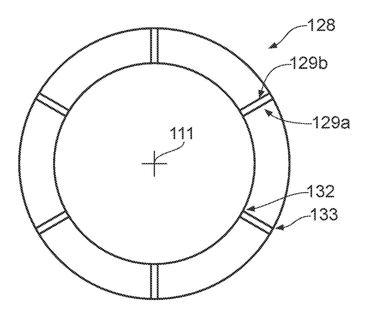
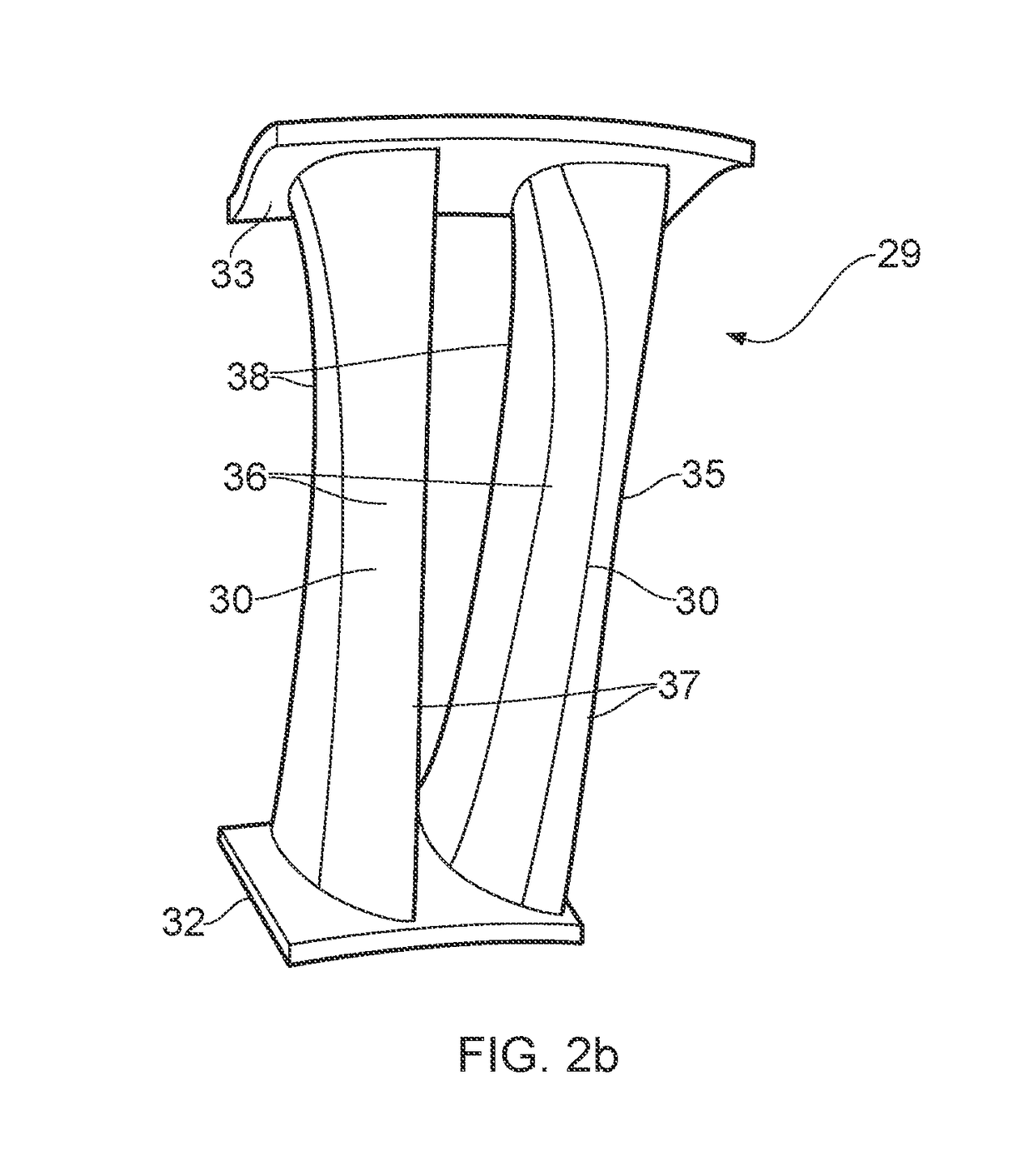
[0045]The gas turbine engine 10 works in the conventional manner so that air entering the intake 12 is accelerated by the fan 13 to produce two air flows: a first air flow 24 into the intermediate pressure compressor 14 and a second air flow 25 which passes through a bypass duct 22 to provide propulsive thrust. Within the bypass duct 22, the second air flow 25 is directed towards the rear of the gas turbine engine by one or more outlet guide vane (OGV) stages 28, ...


PUM


Abstract

A stator arrangement for use in a gas turbine engine, the arrangement comprising an inner outlet guide wall having a central axis, the inner outlet guide wall comprising a first aerofoil extending radially relative to the central axis; the an inner outlet guide wall further comprising a second aerofoil extending radially relative to the central axis, the second aerofoil being relatively displaceable between a first position and a second position; the first aerofoil combining with the second aerofoil to form a combined aerofoil when the second aerofoil is in the first position, and separating to form two or more aerofoils when the second aerofoil is relatively displaced, in use, from the first position towards the second position; wherein one or more of a profile, shape or configuration of the second aerofoil, when in the second position, are substantially identical to that of the first aerofoil.

Description

CROSS-REFERENCE TO RELATED APPLICATIONS[0001]This application is based upon and claims the benefit of priority from British Patent Application No. GB 1708050.8, filed on 19 Mar. 2017, the entire contents of which are hereby incorporated by reference.BACKGROUNDTechnical Field[0002]The present disclosure concerns a stator arrangement. In particular, the present disclosure concerns a stator arrangement for use in a gas turbine engine.Description of the Related Art[0003]During operation of a gas turbine engine, it is common for an amount of noise to be produced. Noise may be produced in several areas of a gas turbine engine including, for example, one or more of the fan, compressor, combustor, and turbine sections. In particular, the compressor system may comprise a low pressure (LP) system. The LP system may comprise a rotor and a number of vanes, known singularly as an outlet guide vane (OGV) or collectively as outlet guide vanes (OGVs). OGVs are commonly located at an outlet of the f...

Claims


Application Information

Patent Timeline
IPC IPC(8): F01D17/16
CPCF01D17/167F05D2220/32F01D5/146F01D9/04
Inventor CARUGNO, PIERA
Owner ROLLS ROYCE PLC
Why Eureka
Try Eureka