Tire Management System

a technology of tire management and tire, applied in the direction of tire measurement, vehicle components, transportation and packaging, etc., can solve the problems of increasing the number of times the cell cannot be replaced, the processing performed by the sensor module, and the cell is exhausted more severely, so as to reduce the number of cell replacements, eliminate cross-talk, and increase the consumption of the cell

Inactive Publication Date: 2007-11-01
BRIDGESTONE CORP
View PDF8 Cites 14 Cited by
  • Summary
  • Abstract
  • Description
  • Claims
  • Application Information

AI Technical Summary

Benefits of technology

[0021] With the first aspect of the present invention, the sensor module measures the tire status value with a cycle that is shorter than the transmission cycle of the data demand signal from the receiver module, and transmits, as soon as it has been judged that the measured data is out of a predetermined normal range, the measured data and a data indicating abnormal state to the receiver module. Additionally, the transmission of the abnormal state data based on the judgment is performed using an abnormal state data transmission exclusive channel. Thus, except for the timing of transmission and reception relating to the data demand, it is possible for the receiver module to positively receive the abnormal state data even if it has been abruptly transmitted, by monitoring the abnormal state data transmission exclusive channel, thereby allowing the sensor module to deliver the transmitted abnormal state data to the receiver module without any delay. Moreover, in a normal state of the tire status value, the sensor module transmits the measured data to the receiver module with a longer cycle in a conventional manner, without significant increase in consumption of the cell.
[0022] With the second aspect of the present invention, the frequency range of the response signal channel is a channel selected from a plurality of predetermined channels having frequency ranges that do not overlap with each other, and the selection of the response signal channel is done by designating the channel by means of the data demand signal transmitted from the receiver module. Thus, the data transmission from the sensor module is limited to a narrow band, besides that the receiver module designates in advance the channel to be used by the sensor module and ready for receiving the transmission from the sensor module through the designated channel. Therefore, in connection with transmission of the response signal based on the data demand signal also, the receiver module is capable of receiving the data from the sensor module with a high reception probability.
[0023] With the third aspect of the present invention, the tire management system includes a plurality of abnormal state data transmission exclusive channels, and the sensor module uses a selected one of the abnormal state data transmission exclusive channels for transmitting the measured data that is out of the normal range. Thus, by selecting a channel out of a plurality of abnormal state data transmission exclusive channels such that the selected channel does not overlap with the frequency band used by other communication systems, it is possible to eliminate cross-talk with the signals of other communication systems and thereby perform transmission and reception of the abnormal state data positively, and at higher speed.
[0024] With the fourth aspect of the present invention, each sensor module has an identification code for identifying the individual sensor module itself. Thus, even if cross-talk occurs with the signals of other communication systems, it is possible to judge whether the signal received is the desired signal, based on the identification code, so as to eliminate erroneous signal reception.
[0025] With the fifth aspect of the present invention, the transmission performed by the sensor module to the receiver module when it has been judged that said data is out of the normal range comprises setting an abnormal flag t to a value indicating the abnormal state, and transmitting, if a consecutive number of times of acquisition of the measured data deviating from the normal range is not larger than a predetermined integer N1, the nearest measured data and an abnormal flag data to the receiver module by a predetermined number of times N2, with a third cycle T3 that is smaller than said second cycle T2. Thus, it is possible to maximize the reception success probability of the transmission to the receiver module, while preserving a satisfactory cell life.
[0026] With the sixth aspect of the present invention, in connection with the transmission based on judgment of the occurrence of the abnormal state, the maximum number N1 of times of the consecutive transmission at the short cycle T2 is made smaller than a ratio T1 / T2. Thus, the transmission is not performed over a long period larger than the long cycle T1 so as to eliminate premature exhaustion of the cell. Furthermore, when the tire is removed form the vehicle and stored in a deflated state, even though the sensor module performs the measurement at a second cycle T2, the transmission is not performed so as to suppress consumption of the cell.

Problems solved by technology

Furthermore, in order to prevent the dropping or damages to the sensor module due to vibration or deformation of the tire, the sensor module is secured in adhesion to the inner surface of the tire by baking or the like, so that the cell cannot be replaced in many instances.
Among others, the processing performed by the sensor module, which consumes the maximum power, is the data transmission to the receiver module.
The larger the number of measured data transmission per unit time, the more severely is the cell exhausted to shorten the cell life.
However, it has been confirmed that, due to a long transmission cycle, when an abnormal state occurs abruptly, such as the drop of the tire pressure, there may be instances that a long time elapses until the occurrence of abnormal state is received by the receiver module, with the result that the abnormal state cannot be properly overcome.

Method used


Image

  • Tire Management System
  • Tire Management System
  • Tire Management System

Examples


Embodiment Construction

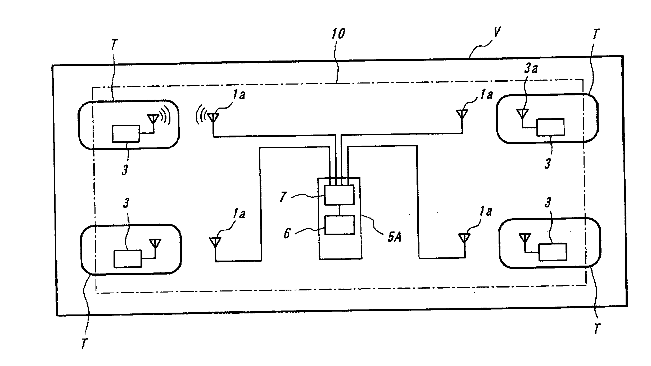
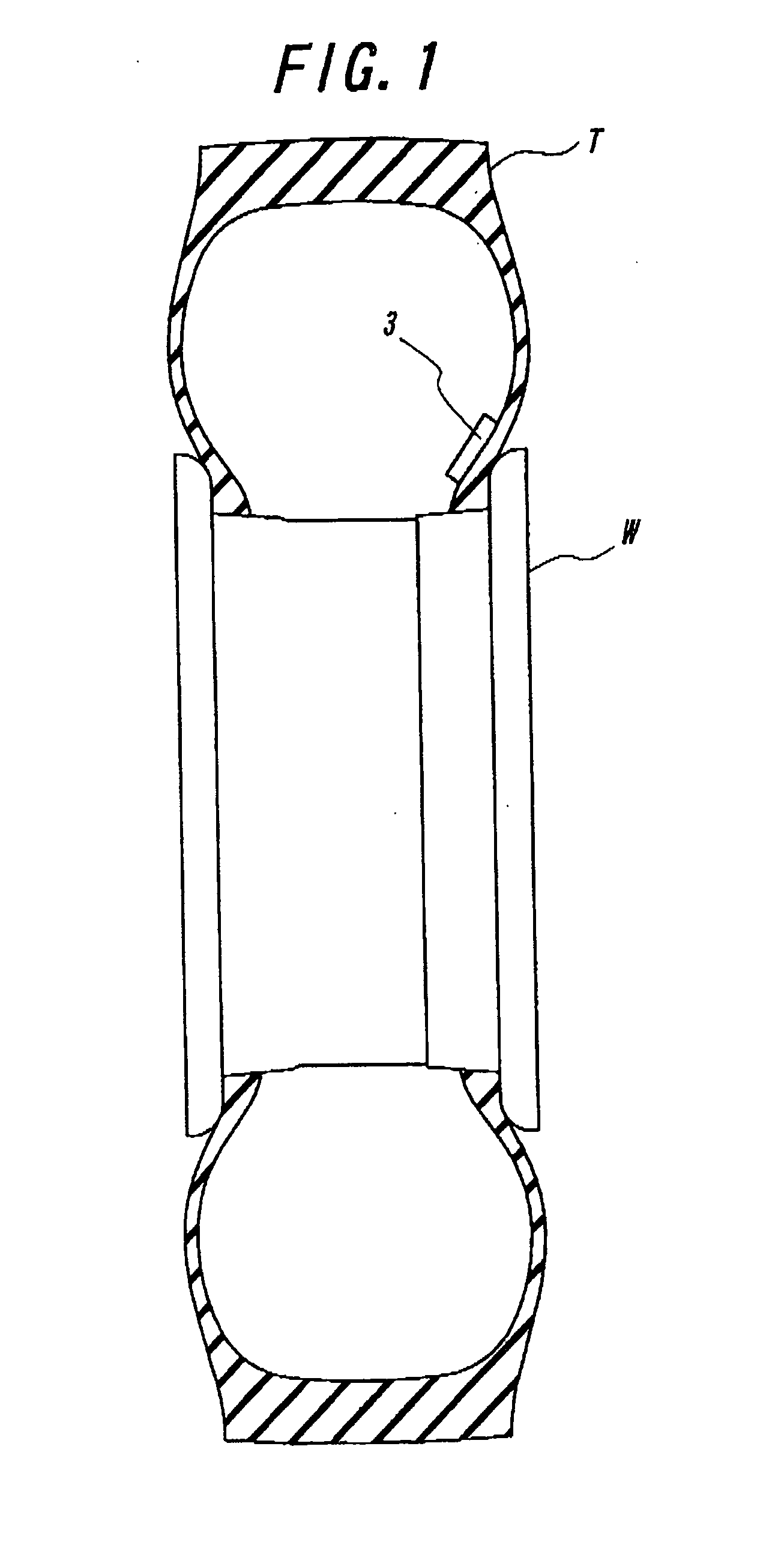
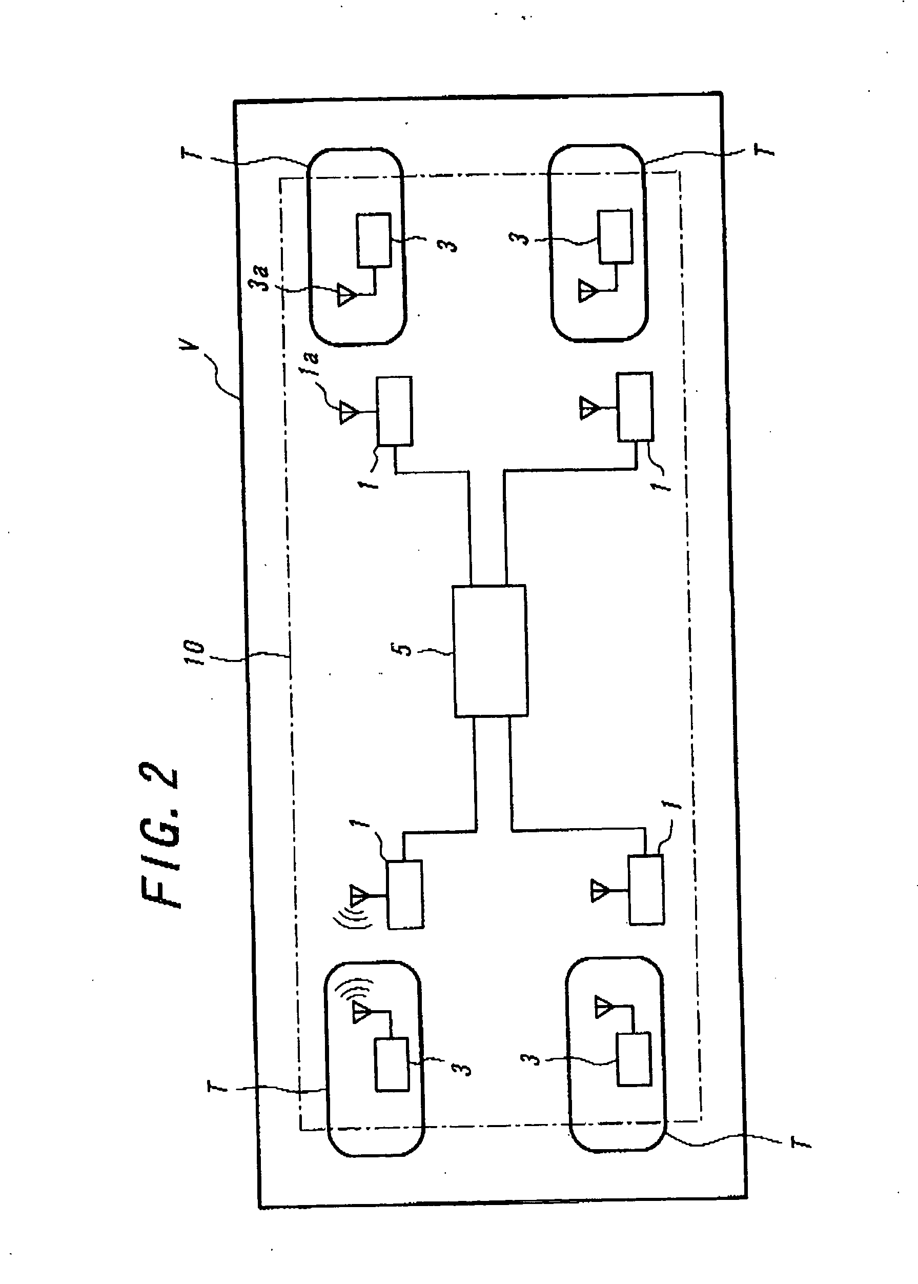
[0039] The present invention will be further described below with reference to preferred embodiments illustrated in the accompanying drawings. FIG. 1 is a sectional view of a sensor module that is secured to the inside of a tire, and FIG. 2 is a schematic view showing the constitution of the tire management system. It can be seen that sensor modules 3 are secured inside of the respective tires, which are mounted on a vehicle V.

[0040] In the illustrated embodiment, the sensor module 3 is secured to the inner surface of a tire T by baking, so as to prevent it from separation or damages even when the tire during the running undergoes deformation under load. The sensor module 3 is comprised of a detector means for detecting tire pressure or the like, an antenna 3a and transmitter for data reception and transmission with a receiver module 1, and a controller means for controlling these elements. The detector means may comprise a detector for detecting the tire temperature, other than th...


PUM


Abstract

A tire management system includes a sensor module secured to inside of a tire that is mounted on a vehicle, for measuring a tire state value and transmitting the measured data to the vehicle side, and a receiver module secured to the vehicle side for transmitting a signal demanding the measured data to the sensor module at a predetermined cycle and receiving the measured data transmitted from the sensor module. The sensor module measures a tire status value at a predetermined cycle, judges whether the measured data is out of a predetermined normal range, and immediately transmits the measured data and an abnormal state data through a predetermined channel exclusively used for transmitting the abnormal state data to the receiver module, if the data is judged to be out of the normal range. With this structure, if an abnormal state occurs, the receiver module can receive the abnormality without any delay, while preventing shortening of the cell life.

Description

TECHNICAL FIELD [0001] The present invention relates to improvement in a tire management system including a sensor module secured to inside of a tire mounted on a vehicle, for measuring a tire status value inclusive of a tire pressure, and a receiver module secured to the vehicle body side, for receiving the measured data transmitted form the sensor module. BACKGROUND ART [0002] In order to perform management of tires in use, there is known a proposal for mounting a tire management system onto a vehicle, wherein a sensor module is secured to inside of a tire, for measuring a tire status value inclusive of the pressure or temperature of the tire. In this instance, the measured data transmitted from the sensor module is received by a receiver module on the vehicle body side, and the received data is transmitted to a vehicle operation-managing center for managing operation of a plurality of vehicles. According to this proposal, based on the data of the tire management system of each ve...

Claims


Application Information

Patent Timeline
Patent Type & Authority Applications(United States)
IPC IPC(8): B60C23/00B60C23/04
CPCB60C23/0464B60C23/0408B60C23/0442B60C23/0462
Inventor ODA, KEIJITAKAO, KOJI
Owner BRIDGESTONE CORP
Why Eureka
Try Eureka