
Sensor component including a microelectromechanical z inertial sensor and method for ascertaining an acceleration with the aid of the microelectromechanical z inertial sensor

a microelectromechanical and sensor technology, applied in the direction of acceleration measurement using interia forces, fluid speed measurement, instruments, etc., can solve the problems of change in the capacitance of the measuring electrode, unavoidable close arrangement of the components, temporally variable temperature gradients between, etc., to achieve the effect of reducing temperature gradients occurring within a shared cavity and being easy to manufactur

Pending Publication Date: 2022-03-24
ROBERT BOSCH GMBH
View PDF7 Cites 0 Cited by
  • Summary
  • Abstract
  • Description
  • Claims
  • Application Information

AI Technical Summary

Benefits of technology

This patent describes a sensor component that includes two sensor elements designed to detect accelerations in the z direction. The sensor elements are made up of a seismic mass structure that is elastically deflectable with respect to a substrate using a torsion spring. The seismic mass structures have different perforations on their heavy and light sides, which cause different responses to temperature gradients in the z direction. An evaluation circuit is included to determine the acceleration in the z direction based on the deflection of the seismic mass structures and use it to correct the measurement. The sensor elements can be designed to have the same sensitivity to z accelerations and different sensitivities to temperature gradients, or to have the same sensitivity to both. The sensor elements can be placed parallel or anti-parallel to each other to optimize sensitivity and reduce temperature gradients. This design helps to accurately detect the presence of vertical temperature gradients and improves the measuring accuracy and reliability of the inertial sensor.

Problems solved by technology

A particularly close arrangement of the components is unavoidable, in particular in products in the so-called consumer market (e.g., smart watches), due to space limitations (small volume and limited lateral extension).
This results in temporally variable temperature gradients between the CPU chip and the adjacent components, for example a MEMS sensor.
The varying expansion of the contained gas, in turn, results in a deflection of the z rocker and thus in a change in the capacitance of the measuring electrodes, which is erroneously interpreted as acceleration.

Method used


Image

  • Sensor component including a microelectromechanical z inertial sensor and method for ascertaining an acceleration with the aid of the microelectromechanical z inertial sensor
  • Sensor component including a microelectromechanical z inertial sensor and method for ascertaining an acceleration with the aid of the microelectromechanical z inertial sensor
  • Sensor component including a microelectromechanical z inertial sensor and method for ascertaining an acceleration with the aid of the microelectromechanical z inertial sensor

Examples


Embodiment Construction

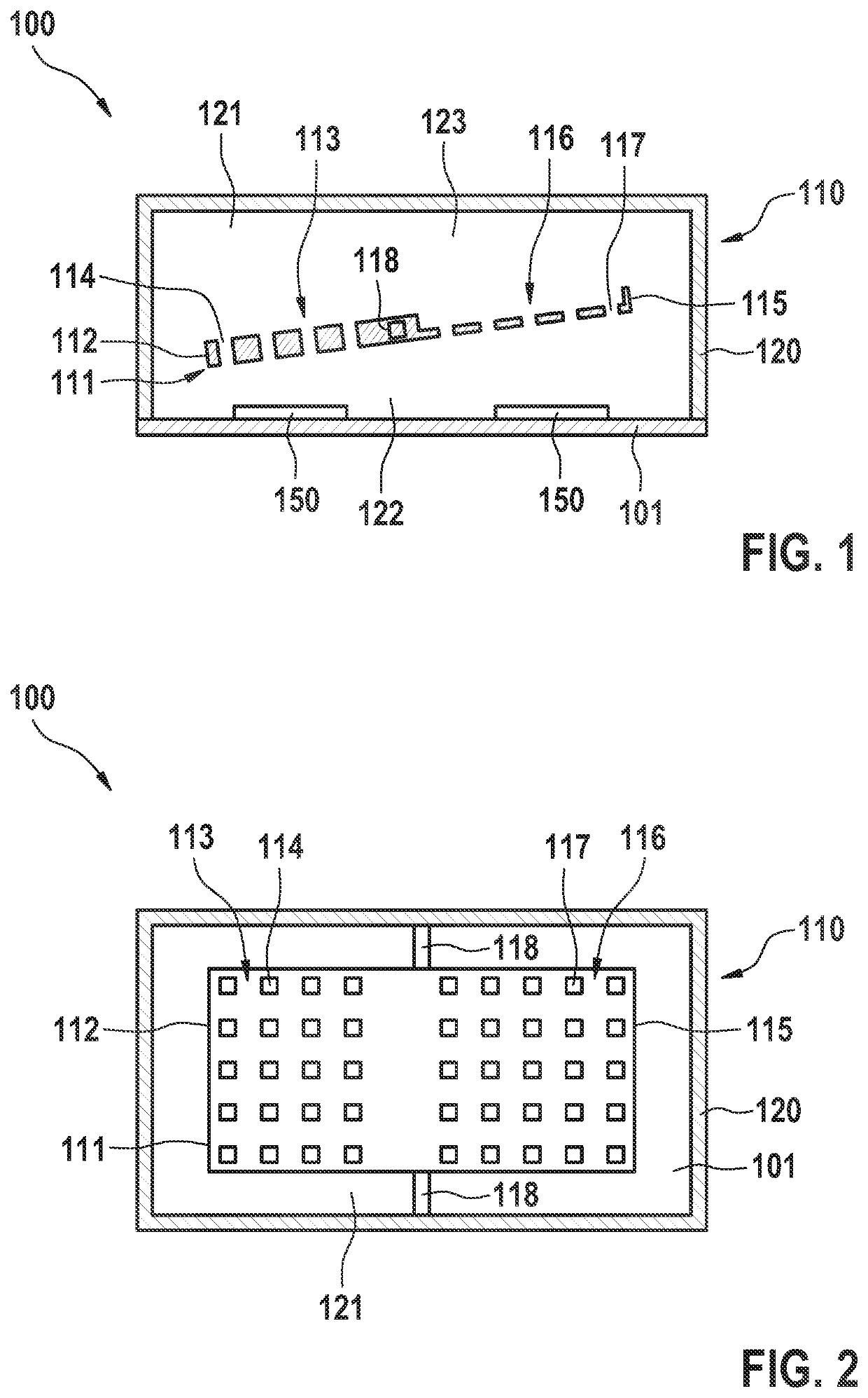
[0026]FIG. 1 shows a microelectromechanical z inertial sensor, including a rocker-shaped MEMS sensor element 110. Sensor element 110, which is situated in a cavity 121 delimited by substrate 101 and a cover-shaped sensor housing 120, includes a seismic mass structure 111, which is anchored on the substrate via one or multiple torsion springs 118 and which is generally created by structuring a function layer situated on a substrate 101. Seismic mass structure 111 has a heavy side 112 and an oppositely situated light side 115 with regard to torsion springs 118. Due to the asymmetrical mass structure distribution resulting therefrom, a deflection of the rocker is effectuated in the presence of an acceleration in the z direction. The deflection of seismic mass structure 111 may be measured capacitively, for example. For this purpose, two electrodes 150 are situated on substrate 101 in FIG. 1, whose electrical potential measurably changes upon a deflection of seismic mass structure 111, ...


PUM


Abstract

A sensor component. The sensor component includes a microelectromechanical z inertial sensor, including two sensor elements situated on a substrate and each designed in the form of a z rocker. The sensor elements each includes a seismic mass structure, elastically deflectable with respect to the substrate with the aid of a torsion spring, which has a heavy side and an oppositely situated light side with regard to the torsion springs. The seismic mass structure of the two sensor elements have different perforations on its heavy and / or light side(s), which effectuate a different sensitivity of the two sensor elements to a temperature gradient running in the z direction. The sensor component also includes an evaluation circuit designed to ascertain an acceleration in the z direction by evaluating the deflection of the seismic mass structure of the two sensor elements.

Description

CROSS REFERENCE[0001]The present application claims the benefit under 35 U.S.C. § 119 of German Patent Application No. DE 102020211924.4 filed on Sep. 23, 2020, which is expressly incorporated herein by reference in its entirety.FIELD[0002]The present invention relates to a sensor component including a microelectromechanical z inertial sensor, which enables a compensation of measuring errors caused by temperature gradients. The present invention further relates to a method for ascertaining an acceleration in the z direction with the aid of the microelectromechanical z inertial sensor.BACKGROUND INFORMATION[0003]Microelectromechanical sensors (so-called MEMS sensors) are used to detect different physical variables, such as pressure, rotation rate or acceleration. Typical MEMS sensors are installed in systems on circuit boards, by which not only interactions exist between the MEMS sensors and the circuit board but also those between MEMS sensors and further components situated on the ...

Claims


Application Information

Patent Timeline
IPC IPC(8): G01P15/125G01P15/08B81B7/00
CPCG01P15/125G01P15/0802B81B2207/03G01P2015/0837B81B2201/0235B81B7/0087G01P2015/0831G01P21/00G01P1/006
Inventor RAMBACH, MARTIN
Owner ROBERT BOSCH GMBH
Learn More