Polarization state rapid tracking monitoring method based on Kalman filtering

A Kalman filter, tracking and monitoring technology, applied in the field of communication, can solve the problems of high implementation cost, only highlighting the convergence speed, increased calculation amount and memory demand, etc., and achieve fast and accurate depolarization, fast convergence speed, and high convergence accuracy Effect

Active Publication Date: 2015-03-04
HARBIN INST OF TECH SHENZHEN GRADUATE SCHOOL
View PDF1 Cites 35 Cited by
  • Summary
  • Abstract
  • Description
  • Claims
  • Application Information

AI Technical Summary

Problems solved by technology

Among them, the depolarization algorithm is an indispensable core algorithm in the new generation of optical communication systems, especially in long-distance transmission optical communication systems, the optical fiber link is subject to many external interference factors, which often cause high-frequency polarization caused by random birefringence State changes, so that the polarization state is aliased and the constellation point of the received signal cannot be distinguished. Therefore, an algorithm that can be quickly tracked is needed to depolarize the state. Fast convergence tracking and monitoring
[0003] At present, the most frequently mentioned depolarization algorithms are constant modulus algorithm (CMA) / multimodulus algorithm (MMA), but these algorithms are in 10 -3 Under the optical signal to noise ratio (OSNR) corresponding to the bit error rate, the limit polarization state rotation rate that can be depolarized is low, close to 1Mrad / s, and its implementation cost is often high
In addition, independent component analysis (ICA), Stokes space method (Stokes space), direct detection least mean square method (decision-directed least mean square, DD-LMS) is also the research of depolarization algorithm However, these methods have their common shortcomings: they often only highlight one of the three aspects of convergence speed, convergence accuracy and calculation amount, while ignoring other aspects
The Kalman polarization state and carrier phase tracking method proposed by Agilent is based on the extended Kalman filter, which makes the received polarization state aliasing signal converge to the desired ideal constellation point to achieve simultaneous depolarization and phase estimation. However, its nonlinear measurement equation greatly increases the calculation and memory requirements of the extended Kalman filter. Especially when dealing with high-order quadrature amplitude modulation signals, such as PDM-16QAM, the measurement equation of the filter needs to be increased, resulting in doubled calculation growth; and since the filter needs to de-bias and phase equalize at the same time, this requires that the signal must be estimated for frequency offset before entering the Kalman filter, or the frequency offset between the local oscillator and the carrier is close to 0, which is for the general heterodyne Detection of coherent receivers is not easy to implement, especially for high-speed high-order QAM modulated coherent communication systems; in addition, the extended Kalman measurement equation uses first-order Taylor myopia for the phase, so the phase equalization ability is limited. When the optical communication system When the linewidth of the lasers at the transmitting end and the receiving end is large, the performance of the coherent optical communication system based on the above algorithm is seriously degraded
Based on the above shortcomings, the Kalman-based channel equalization algorithm proposed in Patent Document 1 can only be applied in some specific coherent receiving environments, and cannot be widely popularized.

Method used


Image

  • Polarization state rapid tracking monitoring method based on Kalman filtering
  • Polarization state rapid tracking monitoring method based on Kalman filtering
  • Polarization state rapid tracking monitoring method based on Kalman filtering

Examples


Embodiment Construction

[0014] The present invention will be further described below in conjunction with the accompanying drawings and specific embodiments.

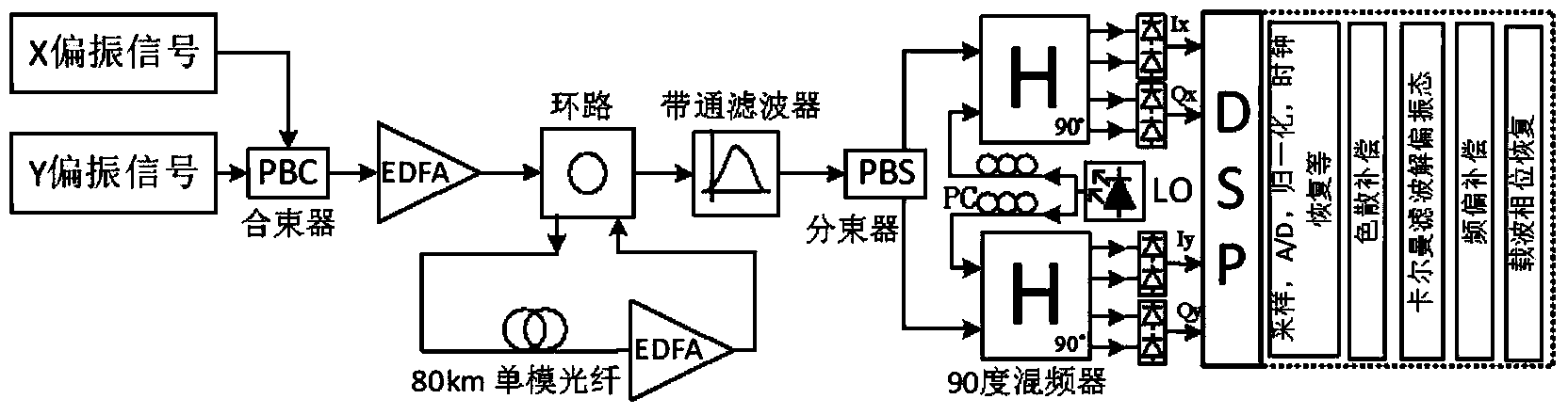
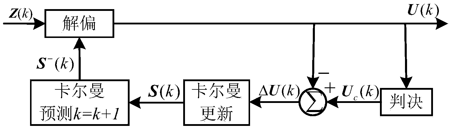
[0015] attached figure 1 It is a structural block diagram of a typical polarization multiplexing coherent optical communication system. The transmitter generates two polarization states of X and Y for combined transmission. After being transmitted through an optical fiber link, a balance detection is performed and converted into four electrical signals, representing two The real (I) and imaginary signal (Q) on the polarization state. After passing through a low-pass filter, the electrical signal enters the digital signal processing module (DSP) for sampling and digital-to-analog conversion. Through digital signal processing, clock recovery, dispersion compensation, depolarization, frequency offset and phase equalization are realized. The method proposed by the present invention belongs to the depolarization algorithm in DSP processing, but is ...


PUM


Abstract

The invention provides a method for performing polarization state tracking and balancing on a received signal in a coherent optical communication system. The method is based on linear Kalman filtering, and comprises the following steps: performing depolarization on an electrical signal input into a filter according to a state vector predicted value to obtain a Kalman measurement predicated value; finding a point which is closest to the measurement predicated value on a circle formed by the rotation of an ideal constellation point for serving as a Kalman practical measured value; subtracting the measurement predicated value from the practical measured value to obtain a measurement allowance, and inputting the measurement allowance into a Kalman updating process; and putting an updated state vector into a next iteration. A highest polarization state rotating speed which can be tracked is about 100 times those of a constant modulus algorithm and a multi-modulus algorithm; the depolarization cost is lowered; the calculation complexity is low; and the calculation amount is small. Moreover, the method is suitable for phase shift keying (PSK) and quadrature amplitude modulation (QAM) polarization multiplexed signals of each order.

Description

technical field [0001] The invention relates to the communication field, in particular to a polarization state tracking monitoring and depolarization method in a coherent optical communication system. Background technique [0002] With the rapid growth of global broadband data services, the amount of data information transmission has surged, and the existing intensity modulation / direct detection (IM / DD) optical communication system can no longer meet the growing demand. A new generation of optical communication systems often adopts such as figure 1 The structure shown combines high-order modulation with polarization multiplexing (PDM) to obtain high spectral efficiency, and uses digital signal processing methods to compensate fiber dispersion, depolarize state, compensate frequency offset, and restore carrier phase. Among them, the depolarization algorithm is an indispensable core algorithm in the new generation of optical communication systems, especially in long-distance ...

Claims


Application Information

Patent Timeline
Patent Type & Authority Applications(China)
IPC IPC(8): H04B10/077H04B10/61
Inventor 杨彦甫曹国亮崔澜涛荣宁谷健姚勇
Owner HARBIN INST OF TECH SHENZHEN GRADUATE SCHOOL
Why Eureka
Try Eureka