System and method for evaluation of fluid flow in a piping system

a fluid flow and system technology, applied in the field of pipe system modeling, can solve the problems of premature corrosion of steel pipes, more difficult to model such piping networks, and fixed topology models that fail to take into account liquid behavior and characteristics,

Active Publication Date: 2010-11-25
TYCO FIRE PRODS LP
View PDF15 Cites 35 Cited by
  • Summary
  • Abstract
  • Description
  • Claims
  • Application Information

AI Technical Summary

Benefits of technology

[0023]The present invention additionally provides for, in yet another preferred embodiment, a process of installing a dry pipe sprinkler system. The process can be achieved by: determining a liquid delivery time of a liquid at a sprinkler head or a nozzle when the sprinkler or nozzle is actuated in a model of a dry pipe sprinkler system; and constructing a dry pipe fire sprinkler system based on the model...

Problems solved by technology

The modeling of liquid and gas flow in piping network presents a situation in which the more detailed the piping network, the more difficult it is to model such piping network.
Often, water is trapped within the pipes and causes freezing problems after the system is put into service.
Another effect of introducing water into the piping network, draining it, and filling the system with air is that any residual moisture can settle and cause premature corrosion within the steel pipe.
As a result of the possibility of failing the required performance test, individuals may choose to develop systems smaller than the maximum system that could be utilized.
The result is that many systems in unheated warehouses, for example, that could cover a maximum of 40,000 square feet are restricted to 25,000 to 30,000 square feet on the basis of the volume limitation.
This results...

Method used


Image

  • System and method for evaluation of fluid flow in a piping system
  • System and method for evaluation of fluid flow in a piping system
  • System and method for evaluation of fluid flow in a piping system

Examples


Embodiment Construction

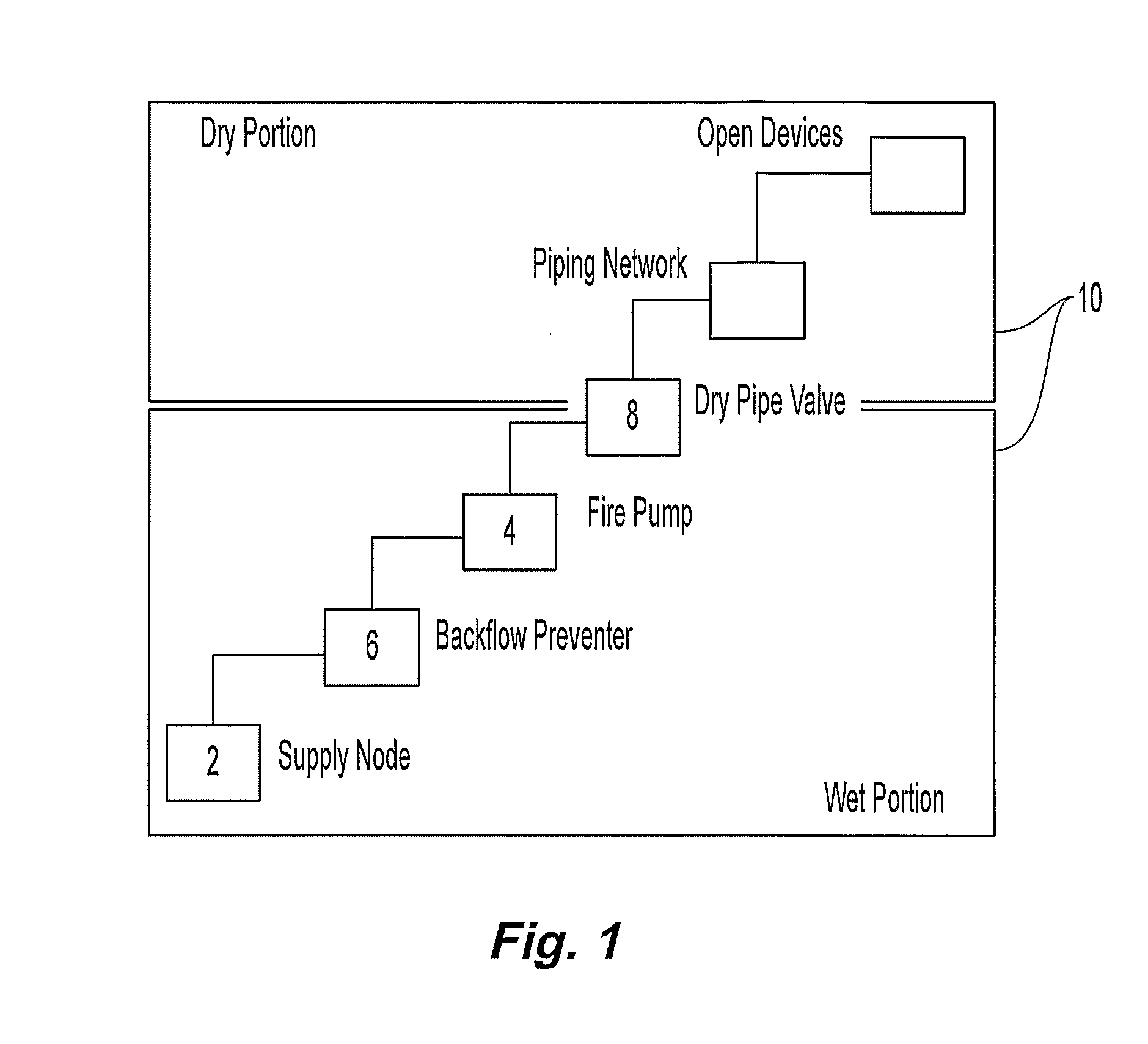
[0052]Shown in FIG. 1 is an illustrative schematic of a dry pipe sprinkler system 10 having a wet portion and a dry portion. The wet portion of the system 10 can include a fluid supply 2 such as, for example, water or a city water main. The wet portion can further include a fire pump 4, configured to increase the pressure of water flow from the supply 2, and a back flow preventer (BFP) 6 configured to maintain fluid flow in one direction, from the wet portion to the dry portion of the system. The dry portion of the system is preferably separated from the wet portion of the system by a dry pipe valve 8 (DPV). The dry pipe valve 8 can be configured to activate or trip to supply the liquid from the wet portion to a network of pipes, pipe fittings, sprinkler heads and / or valves (not shown) downstream of the dry valve. The network of piping downstream of the DPV 8 is filled with a gas such as, for example, air. The DPV 8 can be activated by a drop in pressure downstream of the valve ther...


PUM


Abstract

A method of and a computer program for analyzing models of dry pipe systems. The computer program includes a user interface and a model generator in communication with the user interface. The method and computer program provide for modeling a referential dry pipe system as a plurality of interconnected nodes, the nodes corresponding to a pipe connector, the interconnection between the nodes corresponding to a pipe device. The plurality of nodes can define a dry portion and a wet portion with the wet portion including a liquid source and the dry portion including a plurality of interconnected pipes to define a volume of gas. The nodes in the dry portion can define a set of nodal devices open to ambient. The method and computer program can provide for computing fluid time based parameters to simulate the liquid flowing from the wet portion to determine at least flow time of the liquid from the wet portion to the open devices. The method and computer program can provide for verification of the liquid flow time in the model within 20% of an actual liquid flow time in the referential dry pipe system.

Description

PRIORITY DATA AND INCORPORATION BY REFERENCE[0001]This application claims the benefit of priority to U.S. Provisional Patent Application No. 60 / 722,401, filed Oct. 3, 2005 and which is incorporated by reference in its entirety. Further incorporated herein in its entirety by reference thereto is U.S. patent application Ser. No. 10 / 942,817 filed Sep. 17, 2004, published as U.S. Patent Publication No. 2005 / 0216242, and entitled “SYSTEM AND METHOD FOR EVALUATION OF FLUID FLOW IN A PIPING SYSTEM.” Further incorporated herein in its entirety by reference thereto is software user manual “SPRINKFDT™ SPRINKCALC™: SprinkCAD Studio User Manual” (September 2006).TECHNICAL FIELD[0002]This invention relates generally to pipe system modeling. More specifically, the present invention provides a preferred computerized system and methodology for modeling a dry sprinkler fire protection system to determine time based parameters of performance including, for example, trip time, transit time, and operat...

Claims


Application Information

Patent Timeline
IPC IPC(8): G06G7/50G06F7/60
CPCA62C35/62G05B17/02G06F2217/34G06F2217/16G06F17/5009G06F30/20G06F2111/10G06F2113/14
Inventor GOLINVEAUX, JAMES E.KABASHNIKOV, VITALYMAHOMET, MICHAELMOURACHKO, VALERINIKOLAYCHIK, LEONIDNIKOLAYEV, ALEXANDERPRYMAK, THOMASPOPOV, VALERYBRIL, ANDREYBABENKO, VALERY
Owner TYCO FIRE PRODS LP
Why Eureka
Try Eureka