Method and arrangement for monitoring of an injector

a monitoring method and injector technology, applied in the direction of instruments, liquid transfer devices, exhaust treatment electric control, etc., can solve the problems of not unambiguously pointing out what part of the purification system is not working in a sufficient way, deterioration of catalysts, and insufficient efficiency, so as to improve the nox-purification of exhaust gases, improve monitoring efficiency, and enhance the effect of system functionality

Active Publication Date: 2010-06-10
VOLVO LASTVAGNAR AB
View PDF10 Cites 34 Cited by
  • Summary
  • Abstract
  • Description
  • Claims
  • Application Information

AI Technical Summary

Benefits of technology

[0022]A system for performing the method according to the present invention comprises an After Treatment Substance Injection System (ATSIS) including an After Treatment Injector (ATI). The ATI is located in an engine exhaust system downstream an outlet for exhaust gases from combustion chambers of an engine, e.g. a diesel IC-engine. The ATI is further located upstream of a purification unit in the exhaust gas system, e.g. a filter, catalyst or trap, so as to inject a substance in the exhaust gases in order to enhance a functionality of the system, e.g. the adding o

Problems solved by technology

If the liquid not is injected properly in the exhaust gas stream there will be negative environmental consequences due to malfunctioning of the purification system.
However, these systems have the drawback of not unambiguously pointing out what part of the purification system that is not working in a sufficient way, e.g. it may be that the NOx trap, the filter and/or the catalyst is deteriorated and not working efficiently enough or it may be the ATI which is malfunctioning.
Hence, it is not possible to indicate which part that should be investigated or changed in order to make the system work satisfactorily again.
Furthermore, if the reducing-agent adding unit is clogged, it may be detected by the pressure sensing unit that the pressure downstream from the passage opening/closing valve becomes difficult to be lowered after the valve opening period.
However, even though the system described in EP 1 176 292 describes a system for monitoring an After Treatment Injector, the abo

Method used


Image

  • Method and arrangement for monitoring of an injector
  • Method and arrangement for monitoring of an injector
  • Method and arrangement for monitoring of an injector

Examples


Embodiment Construction

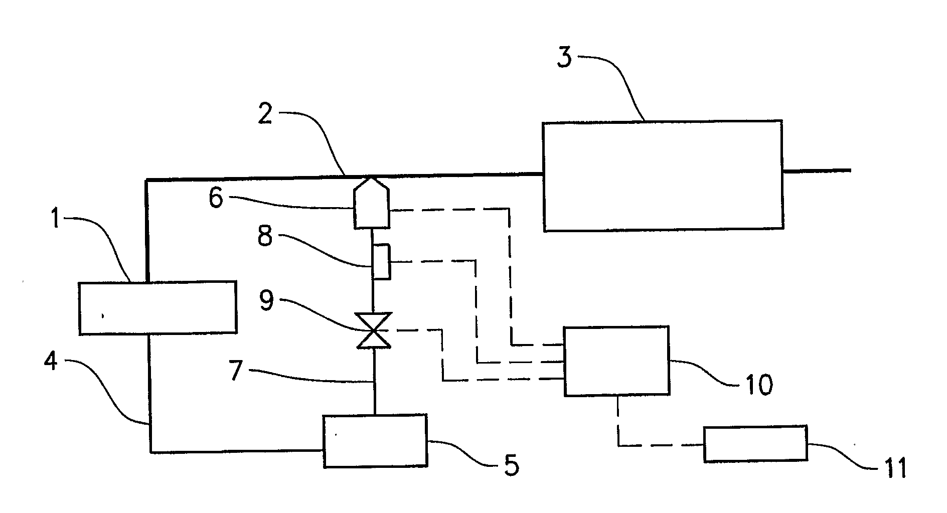
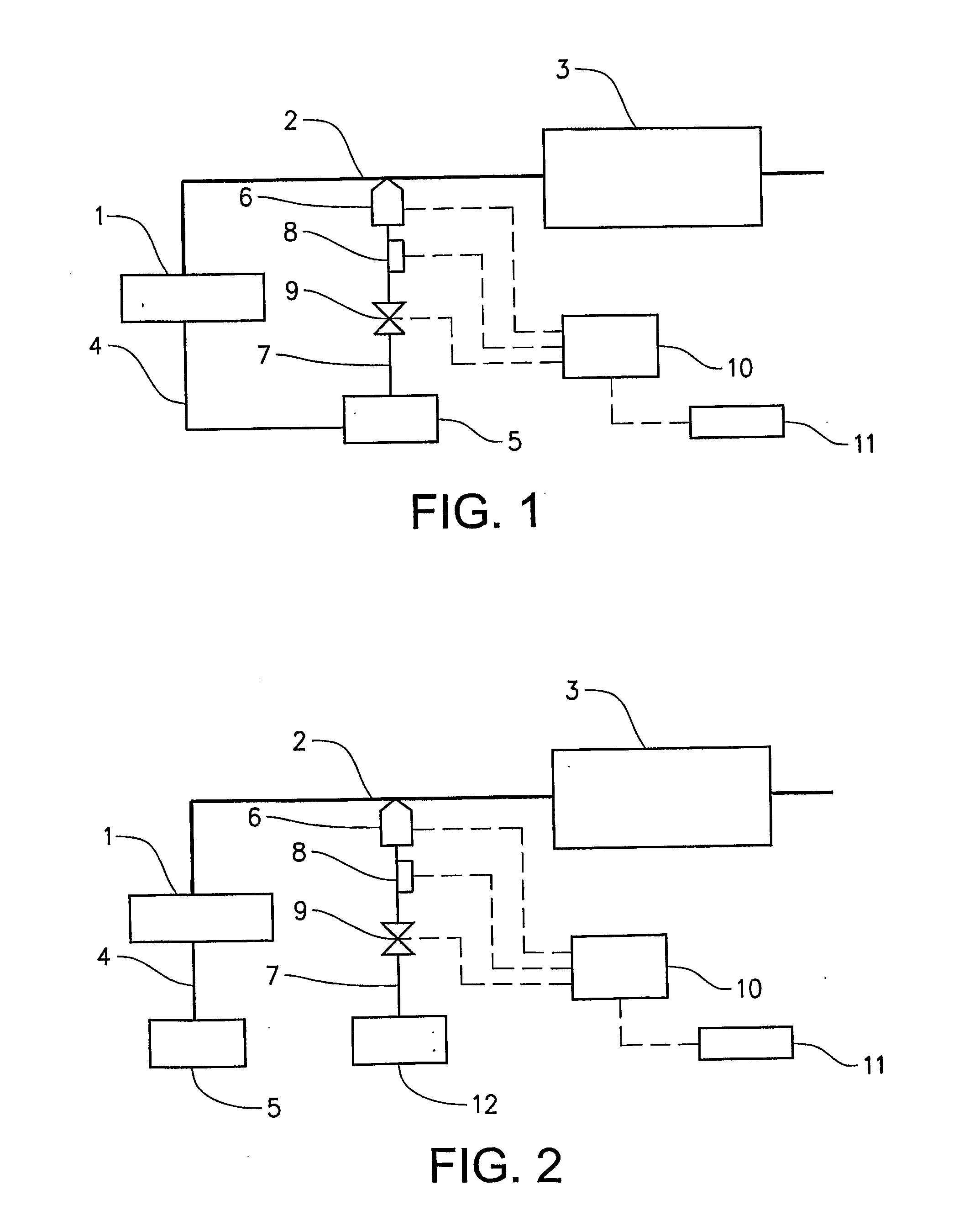
[0045]In FIG. 1 is very briefly described the different parts of an engine exhaust gas system comprising an After Treatment Substance Injection System (ATSIS) according to the invention. An internal combustion engine 1 is connected to an exhaust gas pipe 2 for collecting and guiding of exhaust gases from the engine to an exhaust gas treatment unit 3. The exhaust gas treatment unit 3 may for example be a filter, reduction or oxidation catalyst, NOx-trap or a combination of such treatment devices. Fuel for the engine 3 is supplied by a fuel conduit 4 from a fuel tank 5. An After Treatment Injector (ATI) 6 is located in the exhaust gas pipe 2 downstream of the engine 1 and upstream of the purification unit 3. The ATI 6 is connected to the tank 5 by means of an after treatment substance conduit 7 so as to allow a flow of substance from the tank 5 to the ATI 6. The flow of substance may be caused either due to a pressurized tank or a pumping arrangement. A pressure sensor 8 is located in...


PUM


Abstract

A method and a system are provided for monitoring of the functionality of an After Treatment Injector (ATI) for injection of a fluid in an engine exhaust gas system upstream of an exhaust gas treatment unit. The monitoring is performed by using a pressure sensor which detects the pressure of the fluid delivered to the ATI for a specific condition or injection cycle. The pressure sensor is located downstream of a flow regulator and upstream of the ATI in a conduit for supplying of a substance from a container to the ATI. An ECU is programmed to perform a predetermined sequence of opening and closing commands for the flow regulator and the ATI, furthermore perform a frequency analysis of the measured pressure value in order to monitor the functionality of the flow regulator, the ATI and the pressure sensor. The method and system are adapted to be used in connection with an On Board Diagnosis (OBD) system.

Description

[0001]The present application is a U.S. national stage application of PCT / SE2007 / 000786, filed Sep. 10, 2007, which is a continuation of PCT / SE2007 / 000386, filed Apr. 19, 2007, both of which are incorporated by reference.BACKGROUND AND SUMMARY[0002]The invention relates to a method and a system for monitoring of the functionality of an injector for injection of a fluid in an engine exhaust gas system, a so called After Treatment Injector (ATI). The monitoring is performed by using a pressure sensor which detects the pressure of the fluid delivered from the injector for a specific injection cycle whereby the pressure and pressure fluctuations are registered and compared with reference values in order to indicate the state of the injector. The invention is suitable to be used as a part of the On Board Diagnosis (OBD) system.[0003]In vehicles today, the feature of being able to monitor, regulate and control an exhaust gas purification system comprising a filter and / or catalyst is of ma...

Claims


Application Information

Patent Timeline
IPC IPC(8): F01N9/00F01N3/10
CPCF01N11/00F01N2550/05F01N2560/08F01N2610/02F01N2610/03Y02T10/47F01N2610/146F01N2900/0408F01N2900/0412F01N2900/1808F01N2610/14Y02T10/40
Inventor SEBESTYEN, RICHARDLINGENHULT, ANDERS
Owner VOLVO LASTVAGNAR AB
Why Eureka
Try Eureka