
Wireless apparatus and processing method thereof

a processing method and wireless technology, applied in the field of communication devices, can solve the problems of large frequency deviation of signals received by ups, carrier error and code errors, and uncertainty in code phase, and achieve the effect of enhancing the accuracy of demodulating signals

Inactive Publication Date: 2013-02-21
REALTEK SEMICON CORP
View PDF5 Cites 2 Cited by
  • Summary
  • Abstract
  • Description
  • Claims
  • Application Information

AI Technical Summary

Benefits of technology

The present invention provides a wireless apparatus and processing method that uses a computing circuit to inner product the signal received by the receiving apparatus and produce an output signal. This prevents erroneous outputs from being sent to the compensation circuits due to errors in signal judgment, resulting in improved accuracy of demodulating signals. The wireless receiving apparatus includes a demodulating circuit, computing circuit, and compensating circuit, with the computing circuit adjusting the demodulating circuit based on a compensation signal produced by the compensating circuit. This ensures accurate demodulation of signals.

Problems solved by technology

Besides, the uncertainty in code phase is caused by the unknown initial phase difference and the difference in timing frequencies between the receiver and the satellite.
These differences are so-called carrier error and code error.
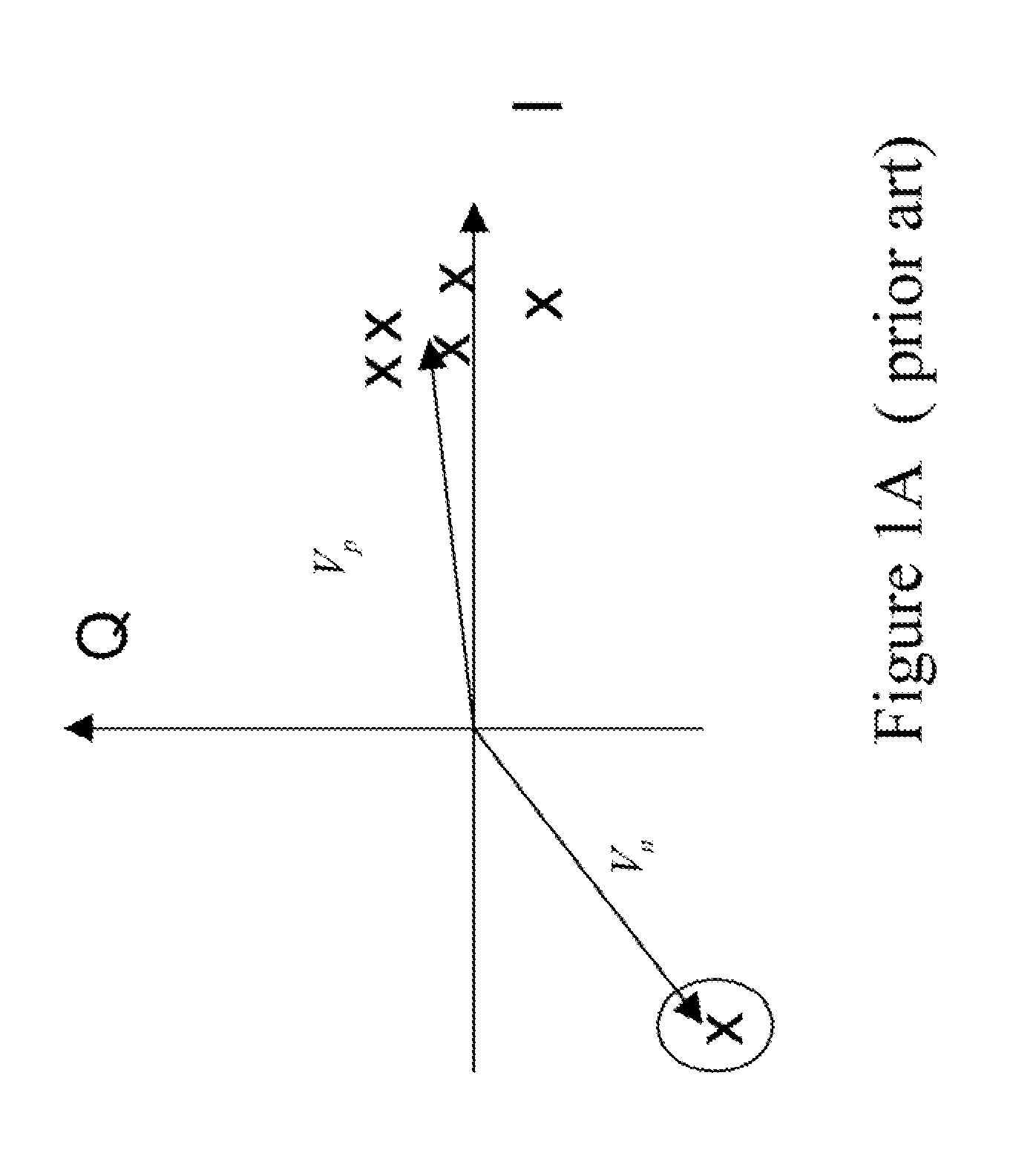
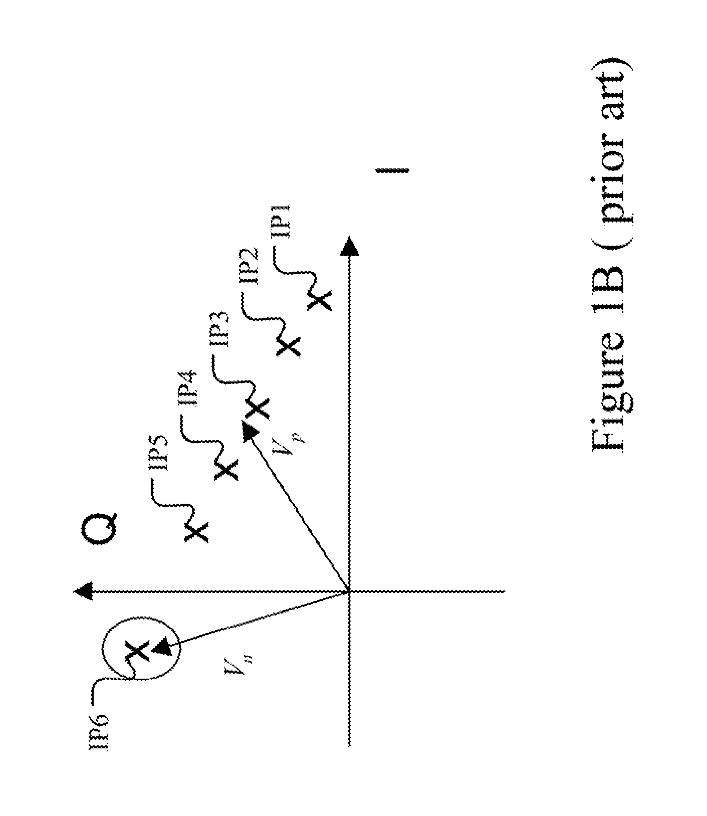
Besides, because the system is disposed in moving objects, such as cars, the signal received by the UPS will encounter the problem of large frequency deviation, caused by the large velocity or acceleration, of the moving objects and the small bandwidth of the loop filter.
The operational circuit, cannot distinguish data bit transition from excess frequency deviation for the received signal, and hence leading to errors while computing the carrier error and the code error, since the symbols multiplying the determined combination are sent to the compensation circuit for computing carrier error and code error.
However, if Fourier transformation is adopted, the complexity and cost of the overall system will become extremely high.

Method used


Image

  • Wireless apparatus and processing method thereof
  • Wireless apparatus and processing method thereof
  • Wireless apparatus and processing method thereof

Examples


Embodiment Construction

[0015]In order to make the structure and characteristics as well as the effectiveness of the present invention to he further understood and recognized, the detailed description of the present invention is provided as follows along with embodiments and accompanying figures.

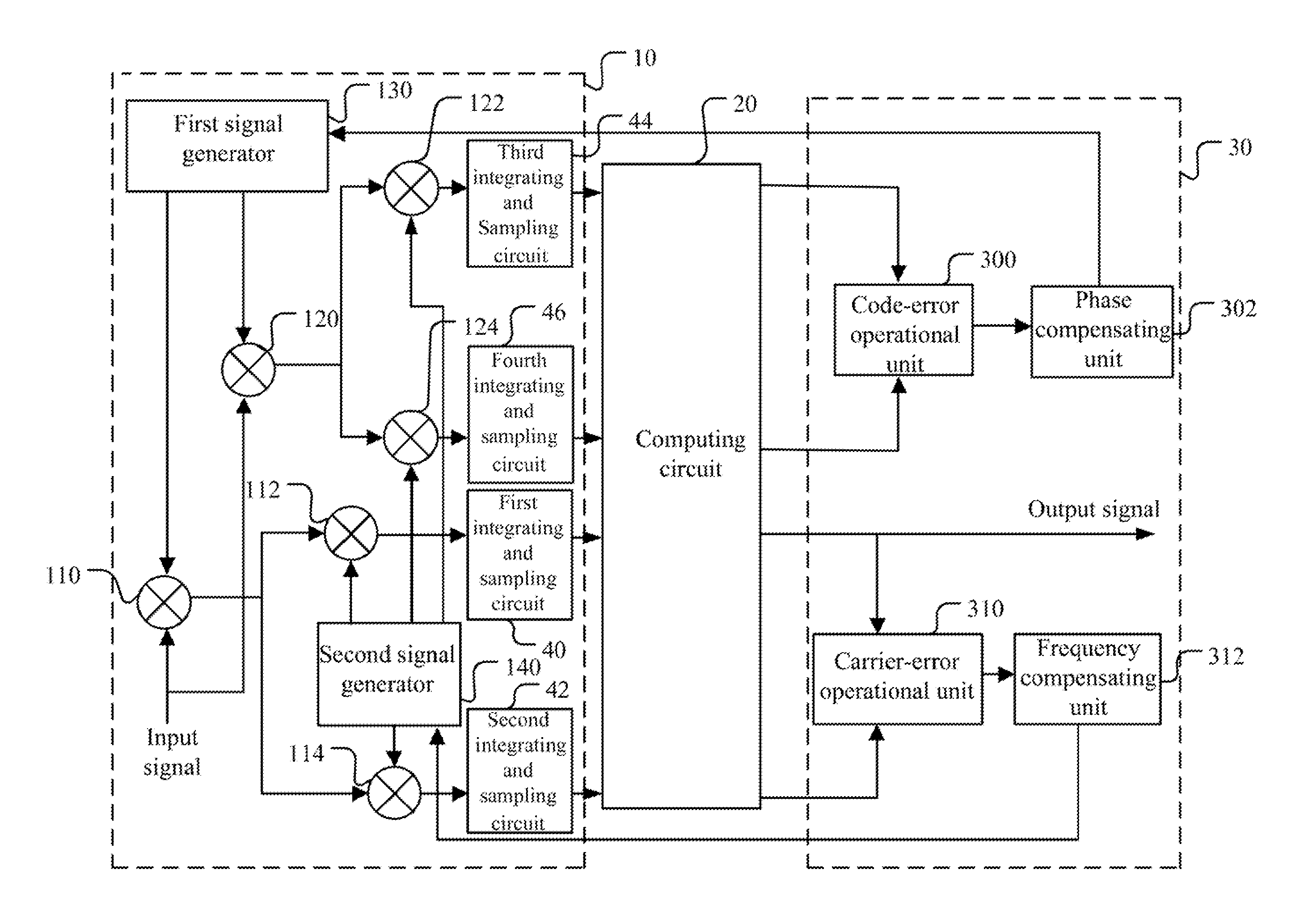
[0016]FIG. 2 shows a circuit diagram according to a preferred embodiment of the present invention. As shown in the figure, the wireless apparatus according to the present invention comprises a demodulating circuit 10, a computing circuit 20, and a compensating circuit 30. The demodulating circuit 10 receives and demodulates an input signal for producing a baseband signal, which includes an I signal and a Q signal. According to the present embodiment, the wireless apparatus according to the present invention is applied, to a spread spectrum system. Thereby, the input signal received by the demodulating circuit 10 is a spread spectrum signal. Then, the demodulating circuit 10 demodulates the spread spectrum signal to...


PUM


Abstract

The present invention relates to a wireless apparatus and the processing method thereof. The wireless apparatus according to the present invention comprises a demodulating circuit, a computing circuit, and a compensating circuit. The demodulating circuit receives and demodulates an input signal for producing a baseband signal. The computing circuit is coupled to the demodulating circuit and receives the baseband signal. It performs inner product on the baseband signal for producing an output signal. The compensating circuit is coupled to the computing circuit, and produces and transmits a compensation signal to the demodulating circuit according to the output signal for adjusting the demodulating circuit. Accordingly, by means of the computing circuit according to the present invention, erroneous outputs sent to the compensation circuit due to erroneous judgment of a signal received with large frequency deviation can he avoided effectively, and hence enhancing the efficiency of the wireless apparatus.

Description

FIELD OF THE INVENTION[0001]The present invention relates generally to a communication apparatus, and particularly to a wireless apparatus and the processing method thereof.BACKGROUND OF THE INVENTION[0002]The receiver in a global positioning system (GPS) needs to have a local oscillator having a highly accurate frequency for acquiring rapidly as well as maintaining synchronization with the carrier frequency, which comes from the satellites, of the GPS. The introduction of GPS will explain the cause of the large frequency deviation in the receiver of a GPS.[0003]If the signal transmitted by a GPS is used for locating, the receiver has to resolve the unknown carrier frequency and the uncertainty in code phase of the spread spectrum signal. The unknown carrier frequency results from the Doppler frequency shift when the satellite and the receiver are moving relatively and from the difference in timing frequencies therebetween. Besides, the uncertainty in code phase is caused by the unk...

Claims


Application Information

Patent Timeline
Patent Type & Authority Applications(United States)
IPC IPC(8): H04L27/06
CPCH04L27/3818G01S19/35G01S19/24
Inventor HOU, KUN-SUI
Owner REALTEK SEMICON CORP
Learn More