
D/A conversion apparatus, decoder, and tape drive

a conversion apparatus and tape drive technology, applied in the field of digital video tape recorders, can solve problems such as detection of input data errors

Inactive Publication Date: 2005-11-15
SONY CORP
View PDF4 Cites 3 Cited by
  • Summary
  • Abstract
  • Description
  • Claims
  • Application Information

AI Technical Summary

Benefits of technology

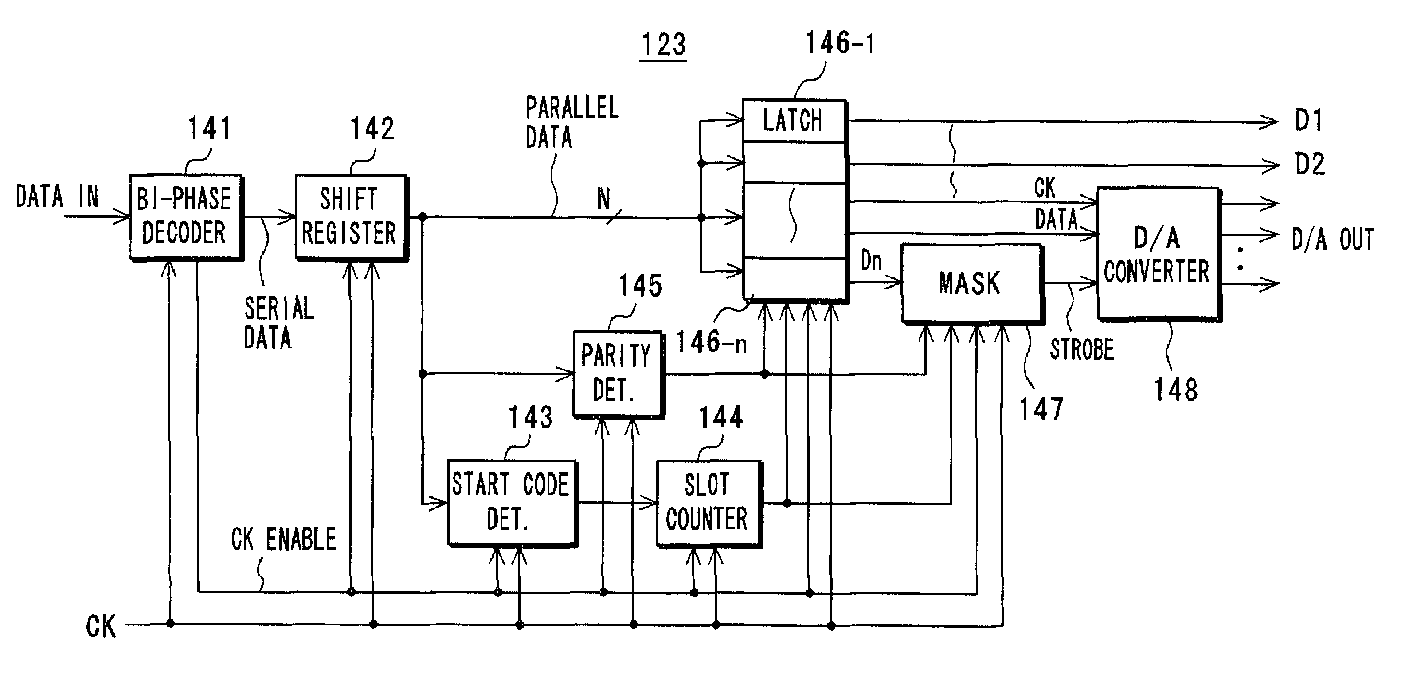
[0047]A D / A conversion apparatus in accordance with one aspect of the invention comprises a D / A conversion section having a serial interface, and error detection means for detecting an error in input data supplied to the D / A conversion section. The D / A conversion apparatus also comprises mask means for masking a strobe signal to be supplied to the D / A conversion section to prevent the D / A conversion section from outputting an analog output signal corresponding to the input data when the error detection means detects the error in the input data.
[0053]Thus, in accordance with the invention, masking the strobe signal supplied to the D / A conversion section prohibits the D / A conversion section having an serial interface from outputting the analog output signal corresponding to the input data when an error is detected in the data supplied to the D / A conversion section, thereby preventing the D / A conversion section from outputting erroneous analog output signal.

Problems solved by technology

An error in the input data is detected, if any.

Method used


Image

  • D/A conversion apparatus, decoder, and tape drive
  • D/A conversion apparatus, decoder, and tape drive
  • D/A conversion apparatus, decoder, and tape drive

Examples


Embodiment Construction

[0073]The following will describe embodiments of this invention with reference to the drawings.

[0074]FIG. 9 shows an embodiment of a digital VTR 100 in its basic configuration according to the invention. For simplicity, description regarding an audio system will be omitted.

[0075]First, a recording system of the VTR will be described. An A / D converter 102 receives an input video signal Vi through input terminal 101, converts it to a digital signal, and transmits the digital signal thus converted to an image compression unit 103. The image compression unit 103 compresses the signal using, for example, a block coding technique. A parity / sync / ID adding unit 104 receives the compressed coded data from the image compression unit 103. The adding unit 104 adds error correction parity, a sync indicative of the beginning of a synchronous block, and an ID code for identification of respective synchronous block (referred to as synchronous block ID) to each synchronous block of the compressed co...


PUM


Abstract

A D / A converter has a serial interface. Of the sets of the data representing multiple control signals output from latch circuits, the data representing input data, the data representing strobe signal, and the data representing clock signal are supplied to the D / A converter. A mask circuit is provided in the path supplying the strobe signal. When a parity detection circuit detects a transmission error, the mask circuit masks the strobe signal to be supplied to the D / A converter, thereby preventing the D / A converter from outputting an analog output signal corresponding to the input data.

Description

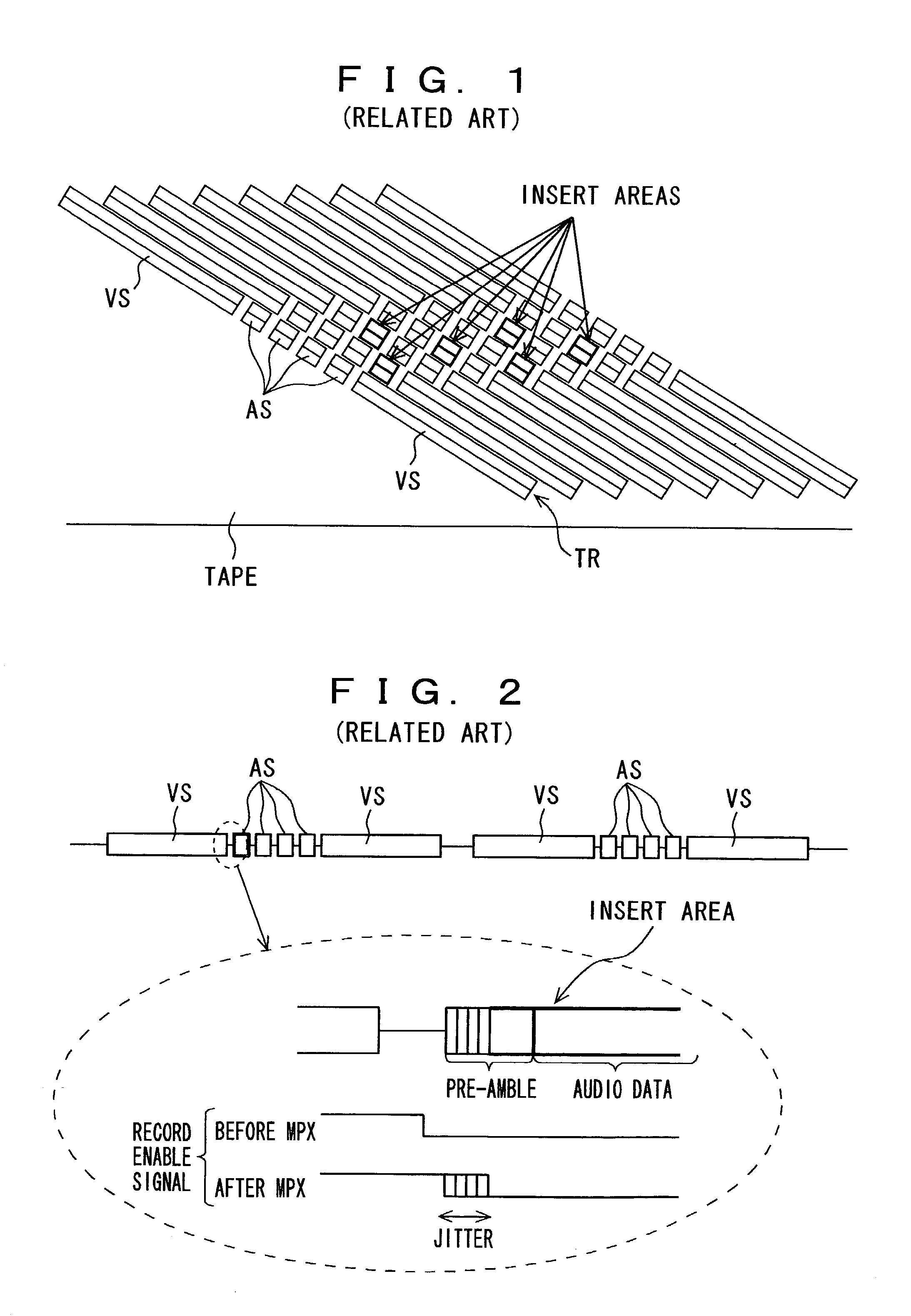
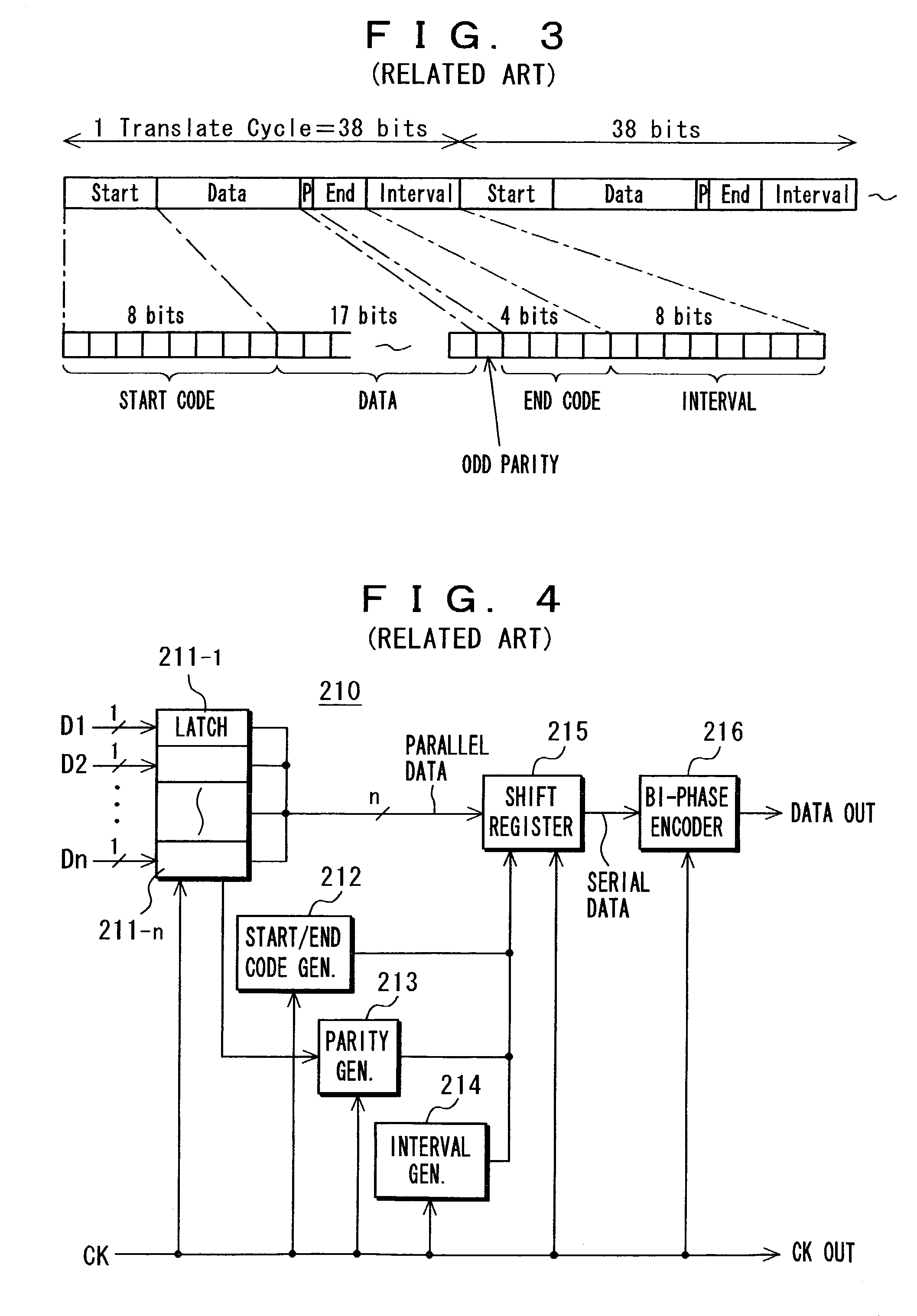
BACKGROUND OF THE INVENTION[0001]1. Field of the Invention[0002]The invention relates to a digital video tape recorder (VTR). More particularly, the invention relates to a digital to analog (D / A) conversion apparatus, a decoder having such D / A conversion apparatus for decoding transmission signals, and a tape drive equipped with such decoder.[0003]2. Description of Related Art[0004]FIG. 1 shows an exemplary tape format for use in a digital video tape recorder (VTR). In track pattern thereof, two video sectors VS and four audio sectors AS are provided on each helical track TR. The four audio sectors AS are disposed between two video sectors VS.[0005]In a conventional VTR, multiple control signals including record enable signals are transferred to devices associated with a rotary drum side via a rotary transformer. The multiple control signals are supplied to the rotary transformer in the form of a serial signal. The devices associated with the rotary drum retrieve the multiple contro...

Claims


Application Information

Patent Timeline
IPC IPC(8): G11B20/18H03M5/12H03M5/00G11B20/14G11B20/10H03M1/66
CPCG11B20/1803H03M5/12
Inventor URATA, KAORUTANAKA, HIROKAZU
Owner SONY CORP
Learn More