Optical sender, terminal device, and optical communication system each having the optical sender

a terminal device and optical communication technology, applied in the direction of transmission monitoring, instruments, semiconductor lasers, etc., can solve the problems of interchannel crosstalk, transmission data cannot be accurately demodulated in a terminal device, unstable wavelength of optical signals to be output from each optical sender,

Inactive Publication Date: 2006-11-07
FUJITSU LTD
View PDF16 Cites 45 Cited by
  • Summary
  • Abstract
  • Description
  • Claims
  • Application Information

AI Technical Summary

Benefits of technology

[0010]It is therefore an object of the present invention to provide an optical sender w

Problems solved by technology

Due to the characteristics of the laser diode as mentioned above, the wavelength of an optical signal to be output from each optical sender tends to be unstable.
For example, in starting up or shutting down the system or in the case of a trouble in relation to temperature control or the like performed in each optical sender, there is a possibility that the wavelength of the optical signal may be deviated from a target wavelength assigned to the corresponding channel, causing the occurre

Method used


Image

  • Optical sender, terminal device, and optical communication system each having the optical sender
  • Optical sender, terminal device, and optical communication system each having the optical sender
  • Optical sender, terminal device, and optical communication system each having the optical sender

Examples


Embodiment Construction

[0042]Some preferred embodiments of the present invention will now be described in detail with reference to the attached drawings. Throughout the drawings, substantially the same parts are denoted by the same reference numerals.

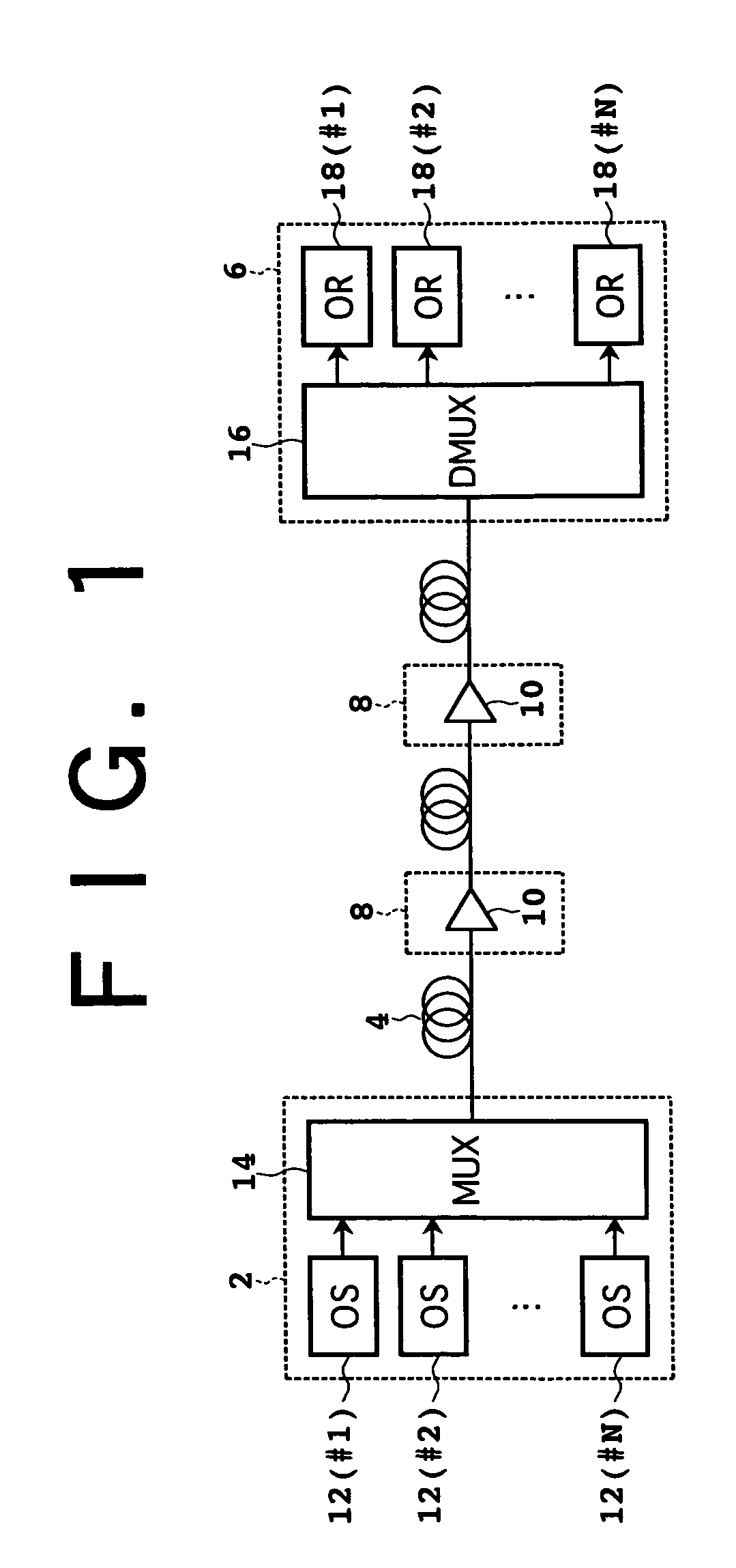
[0043]FIG. 1 is a block diagram of an optical fiber communication system to which the present invention is applicable. This system includes a first terminal device 2 for outputting WDM signal light, an optical fiber transmission line 4 for transmitting the WDM signal light output from the terminal device 2, and a second terminal device 6 for receiving the WDM signal light transmitted by the transmission line 4.

[0044]The first terminal device 2 includes a plurality of optical senders (OS) 12 (#1 to #N) and an optical multiplexer (MUX) 14. The optical senders 12 (#1 to πN) are respectively connected to a plurality of input ports of the optical multiplexer 14. An output port of the optical multiplexer 14 is connected to the optical fiber transmission line 4. The...


PUM


Abstract

The present invention relates to an optical sender applicable to WDM (wavelength division multiplexing), and a primary object of the present invention is to prevent interchannel crosstalk in WDM. The optical sender includes a light source for outputting a light beam, an optical modulator for modulating the light beam in accordance with a main signal to output an optical signal, and a unit for shutting down the optical signal when receiving at least one of a power alarm relating to on/off of power supply and a wavelength alarm relating to the wavelength of the light beam.

Description

BACKGROUND OF THE INVENTION[0001]1. Field of the Invention[0002]The present invention relates generally to prevention of interchannel crosstalk in wavelength division multiplexing (WDM), and more particularly to an optical sender, terminal device, and optical communication system each having the optical sender suitable for application to WDM.[0003]2. Description of the Related Art[0004]Known as a terminal device for WDM using a plurality of wavelength channels is a terminal device including a plurality of optical senders for outputting optical signals having different wavelengths and an optical multiplexer for wavelength division multiplexing the optical signals output from the optical senders to output WDM signal light. The WDM signal light is transmitted through an optical fiber transmission line to another terminal device. By applying such WDM using a plurality of wavelength channels, a large-capacity optical fiber communication system can be provided.[0005]In an optical fiber co...

Claims


Application Information

Patent Timeline
IPC IPC(8): H04B10/08H04B10/04H04J14/02G02F1/025G02F1/035H01S5/00H04B10/07H04B10/077H04B10/079H04B10/2507H04B10/293H04B10/40H04B10/50H04B10/516H04B10/564H04B10/572H04B10/60H04J14/00
CPCH04B10/50575H04B10/564H04B10/572H04B10/07957H04B10/506H04B10/588
Inventor SHIMURA, YOSHITAKASEKIYA, MOTOYOSHIIMAI, KEISUKE
Owner FUJITSU LTD
Why Eureka
Try Eureka