Waveguide combiner system and method with less susceptibility to glare
What is AI technical title?
AI technical title is built by Patsnap AI team. It summarizes the technical point description of the patent document.
a combiner and waveguide technology, applied in the field of displays, can solve the problems of requiring space in the cockpit, and requiring large huds, etc., and achieve the effect of preventing glare through the output grating
Active Publication Date: 2017-03-21
ROCKWELL COLLINS INC
View PDF562 Cites 47 Cited by
Summary
Abstract
Description
Claims
Application Information
AI Technical Summary
This helps you quickly interpret patents by identifying the three key elements:
Problems solved by technology
Method used
Benefits of technology
Benefits of technology
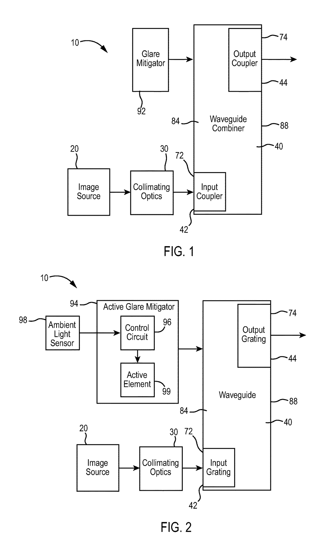
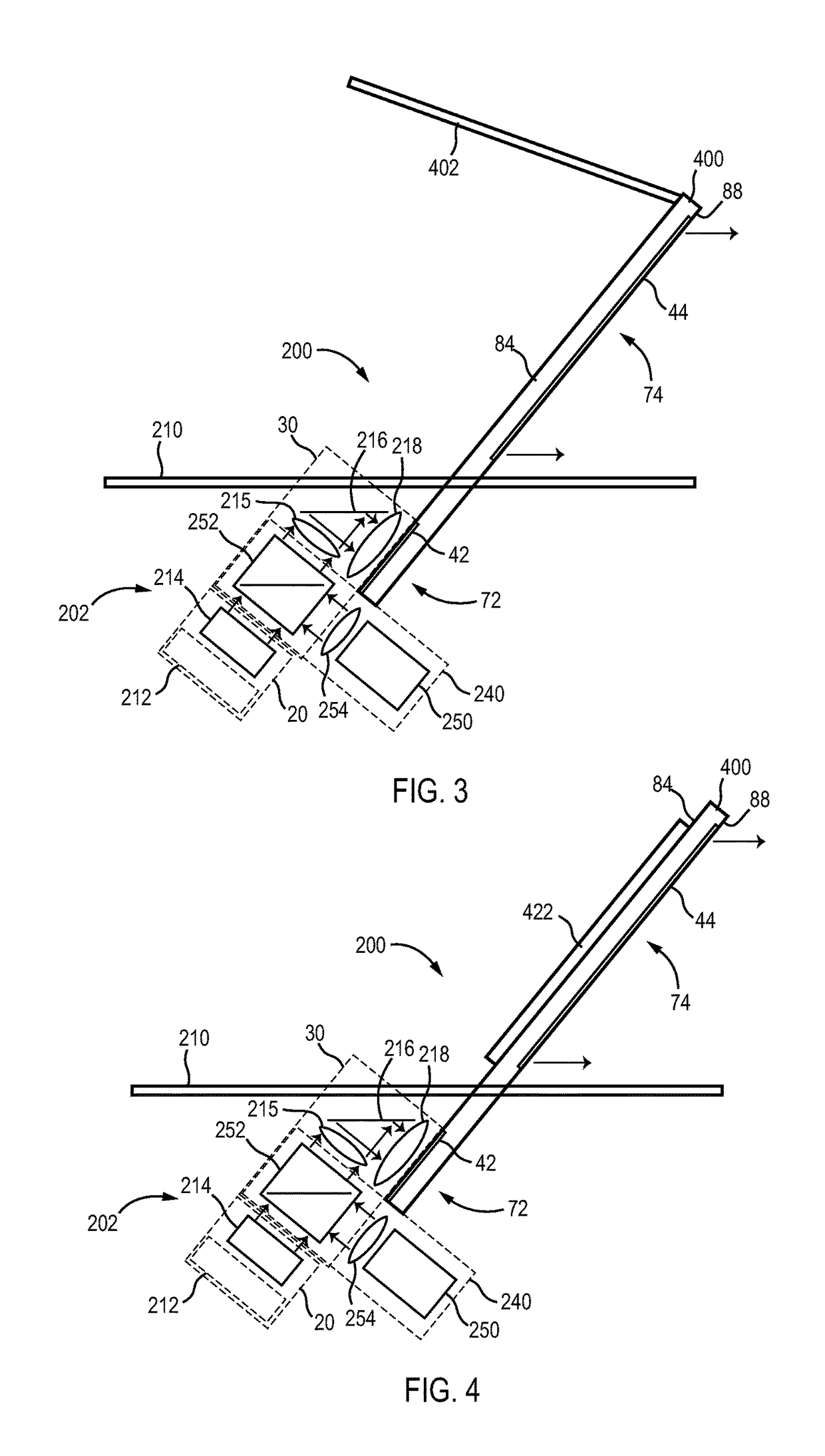
[0008]Another embodiment relates to a head up display including a waveguide combiner and a glare mitigator. The waveguide combiner includes an input grating and an output grating. The glare mitigator is disposed to prevent glare through the output grating from reaching an eye box.
Problems solved by technology
Conventional HUDs are generally large, expensive and difficult to fit into small airplanes.
However, such LADs do not provide HUD capabilities and require space in the cockpit that is required by conventional HUDs.
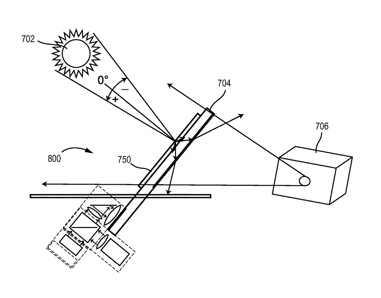
HUDs which use waveguide combiners have a smaller size but can be susceptible to glare or sunspot imaging.
Method used
Image
Click on the blue label to locate the original text in one second.
Reading with bidirectional positioning of images and text.
Examples
Embodiment Construction
[0017]Before describing in detail the particular improved system and method, it should be observed that the invention includes, but is not limited to, a novel structural combination of optical components and not in the particular detailed configurations thereof. Accordingly, the structure, methods, functions, control and arrangement of components have been illustrated in the drawings by readily understandable block representations and schematic drawings, in order not to obscure the disclosure with structural details which will be readily apparent to those skilled in the art, having the benefit of the description herein. Further, the invention is not limited to the particular embodiments depicted in the exemplary diagrams, but should be construed in accordance with the language in the claims.
[0018]With reference to FIG. 1, a head up display (HUD) system 10 can be utilized in various applications, including but not limited to aviation, medical, naval, targeting, ground based, military...
PUM
Abstract
A system and method for a head up display (HUD) can mitigate glare. The head up display can include a waveguide combiner including an input grating and an output grating and a glare mitigator disposed to prevent glare through the output grating from reaching an eye box. The glare mitigator can be a shade, a diffuser, a dimming element, or other device for mitigating glare. The glare mitigator can be an active or passive glare mitigator.
Description
CROSS REFERENCE TO RELATED APPLICATIONS[0001]The present application is related to: U.S. patent application Ser. No. 13 / 892,026, filed on an even date herewith, by Stratton et al., U.S. patent application Ser. No. 13 / 250,940, filed on Sep. 30, 2011 by Stahl et al., U.S. patent application Ser. No. 13 / 251,087, filed on Sep. 30, 2011 by Brown et al.; U.S. patent application Ser. No. 13 / 250,858, filed on Sep. 30, 2011 by Brown et al., U.S. patent application Ser. No. 13 / 250,970, filed on Sep. 30, 2011 by Burns et al., U.S. patent application Ser. No. 13 / 250,994, filed on Sep. 30, 2011 by Wood et al., and U.S. patent application Ser. No. 13 / 250,621, filed on Sep. 30, 2011 by Brown et al., incorporated herein by reference herein in their entireties and assigned to the assignee of the present application.BACKGROUND OF THE INVENTION[0002]The present specification relates to displays. More particularly, the present specification relates to head up displays (HUDs).[0003]Conventional HUDs are...
Claims
Application Information
Patent Timeline
Application Date:The date an application was filed.
Publication Date:The date a patent or application was officially published.
First Publication Date:The earliest publication date of a patent with the same application number.
Issue Date:Publication date of the patent grant document.
PCT Entry Date:The Entry date of PCT National Phase.
Estimated Expiry Date:The statutory expiry date of a patent right according to the Patent Law, and it is the longest term of protection that the patent right can achieve without the termination of the patent right due to other reasons(Term extension factor has been taken into account ).
Invalid Date:Actual expiry date is based on effective date or publication date of legal transaction data of invalid patent.

